- En →
- Zapchasti Kompressorov →
- Kompressory Howden →
- Razborka Xrv163 204 Kompressora
Toros LLC is industrial cold of Europe
Spare parts, repair and maintenance of refrigeration units.
Spare parts for compressors in stock and on order!
call:
WhatsApp
e-mail: storopov86@gmail.com
Complete repair of the XRV 163-204 compressor
Part 1. Dismantling the compressor
Remember that the compressor spool is under spring load, and to avoid injury, the operator should check that the spring is not tensioned before disassembling. This can be done by checking that the spool is fully loaded (the drum must be in the limit position relative to the outlet) and the minimum value for adjusting the liquid coefficient. (The Vi adjusting screw should be turned clockwise to the limit).
1. Place the vessel under the crankcase at the inlet end, remove the hexagonal plug from the bottom of the crankcase at the inlet end, and drain off the oil. (Fig.1)
2. Remove the three mounting screws securing the microswitch cover and remove the cover from the back of the drive cylinder. Some compressors have an LPI sensor, which is installed as an option instead of switches, and do not have a cylinder switch cover.
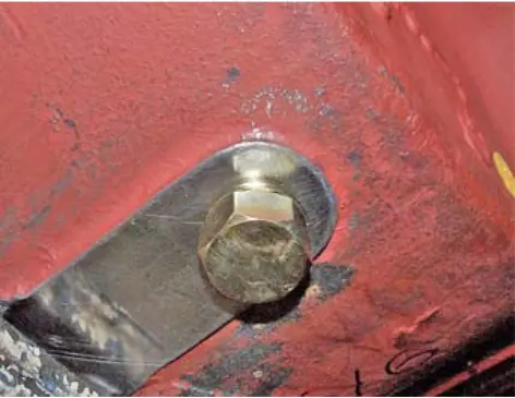 fig. 1. Oil drain
3. Disconnect/remove any installed electrical equipment if it prevents further disassembly.
4. Fully unload the power control valve by turning the square screw clockwise. (Figure 2)
5. Remove the mounting screws, washers and the Vi adjustment unit. (Figure 3)
6. Check the unit and its opening for wear and damage. Remove the o-rings and replace them when reassembling them.
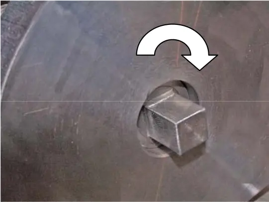 fig. 2. Square power control valve screw fig. 2. Square power control valve screw |
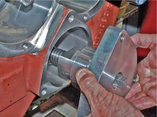 fig. 3. Vi Control Unit fig. 3. Vi Control Unit |
7. Remove the mounting screws and washers that secure the inlet end “female” shaft cover (Figure 4).
8. Remove the inlet end “female” shaft cover using the existing lifting holes. Remove the o-ring and replace it when reassembling it.
9. Loosen and remove the mounting screws and washers on the drive shaft cover. (Figure 5)
10. Remove the drive shaft cover using the existing lifting holes (Figure 6). Remove the shaft seal (Figure 7). Remove the fixed shaft seal seat and sealing ring located in the drive shaft cover.
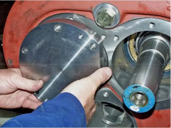 fig. 4. Inlet end “female” shaft cover fig. 4. Inlet end “female” shaft cover |
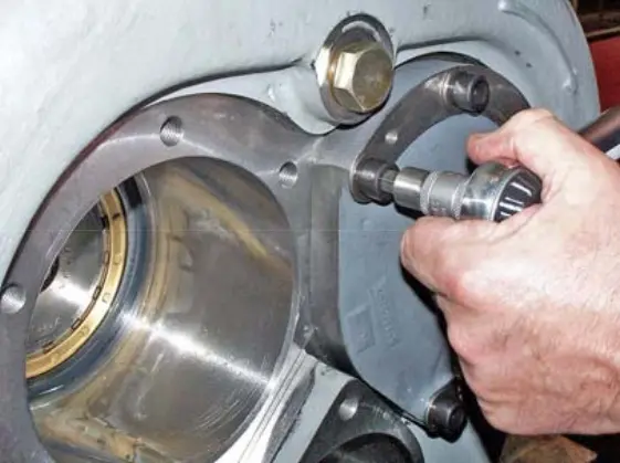 fig. 5. Drive shaft cover fig. 5. Drive shaft cover |
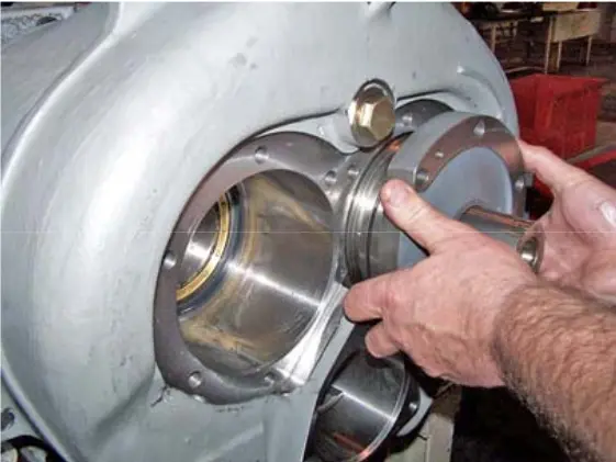 figure 6. Drive shaft cover lifting holes figure 6. Drive shaft cover lifting holes |
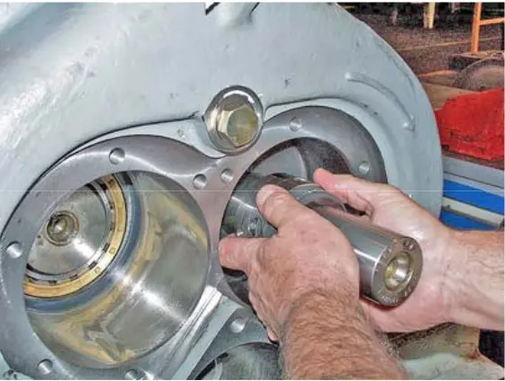 figure 7. Shaft seal figure 7. Shaft seal |
11. Using extraction tools, remove the discharge drum from the drive shaft hole, check the drum and hole for wear and damage. (Figure 8)
12. Remove the two mounting screws located diagonally opposite each other and securing the drive cylinder cover, and replace their screw ties and nuts for safety reasons. (Figure 9)
13. Remove the two remaining mounting screws securing the drive cylinder cover and remove the cylinder cover using ties and nuts until the drum return spring loosens. (Figure 10)
14. Remove the ties and the drive cylinder cover/indicator spindle. (Figure 11) Mark the recess where the guide pin rotates on the indicator spindle to facilitate reassembly. (Not applicable to models equipped with an LPI sensor) Remove and discard the O-ring.
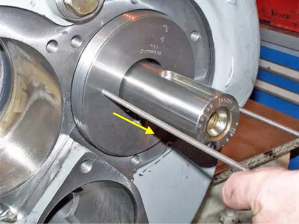 figure 8. Discharge drum figure 8. Discharge drum |
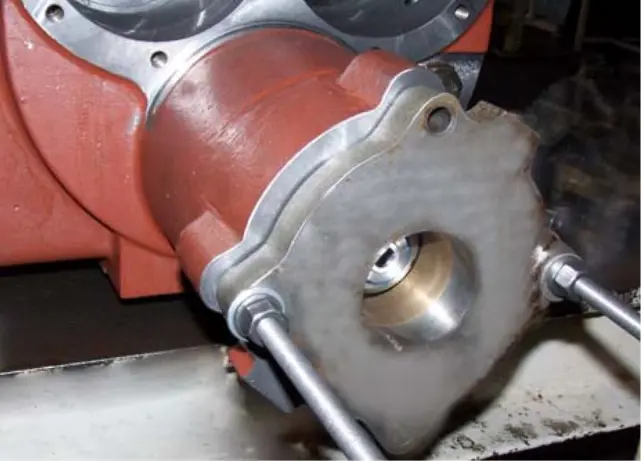 fig. 9. Drive cylinder cover ties fig. 9. Drive cylinder cover ties |
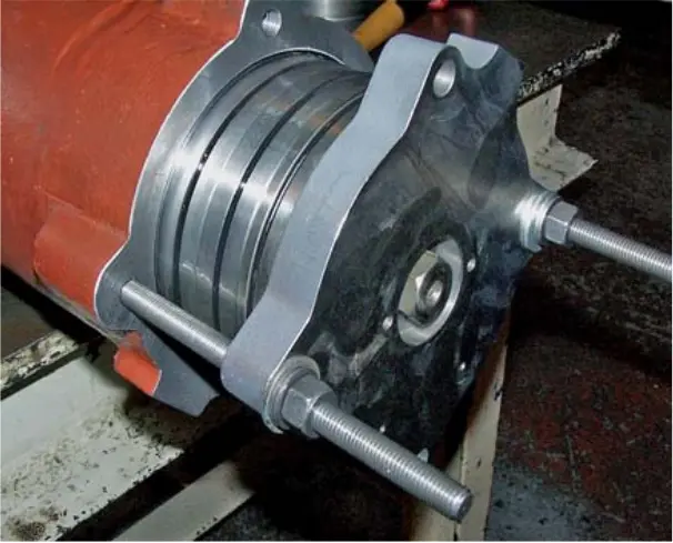 fig. 10. Spring loosening fig. 10. Spring loosening |
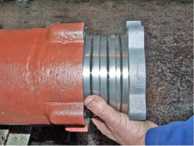 figure 11. Drive cylinder cover/indicator spindle figure 11. Drive cylinder cover/indicator spindle |
15. Remove the locking screw without the M5 head from the lock nut.
16. Unscrew the lock nut that secures the drum using the lock nut wrench.
17. You can then remove the drum using extraction tools.
18. Locate and remove the indicator spindle guide pin. (Only installed on compressors with switches)
IMG12
19. Check the spindle guide pin of the damage indicator. If necessary, replace it.
20. Check the drum and cylinder bore for wear, scuff and debris. (Figure 13)
21. Remove the cuff and replace it when reassembling it. (Figure 14)
22. If the drive drum unit is worn out excessively, contact Howden Compressors Limited's compressor business unit.
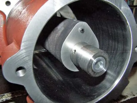 figure 13. Drum and cylinder bore figure 13. Drum and cylinder bore |
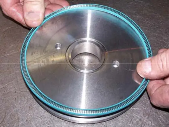 figure 14. Cuff figure 14. Cuff |
23. Before removing the exhaust shaft covers, mark them so that they can be accurately installed later.
24. Remove the mounting screws and washers securing the exhaust shaft covers. (Figure 31)
25. Remove the exhaust shaft covers. Remove the o-rings and replace them when reassembling them. (Figure 32)
26. Remove the spacer from the exhaust housing hole. (On the rotor side “mom”) (Figure 15)
27. Use the rotor attachment tool to secure the “dad” rotor when preparing to remove the exhaust end discharge drum. (Figure 16)
28. Disconnect the spring washer at the end of the “dad” rotor using a small punch and mallet, remove the lock nut. (Figure 17)
29. Remove the discharge drum from its bushing, using extraction tools. (Figure 18)
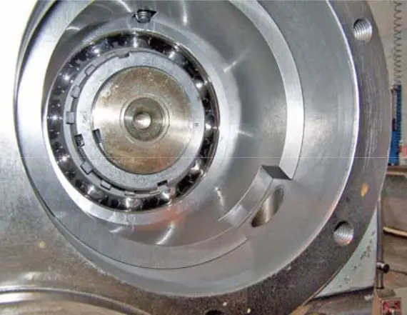 fig. 15. Spacer bush fig. 15. Spacer bush |
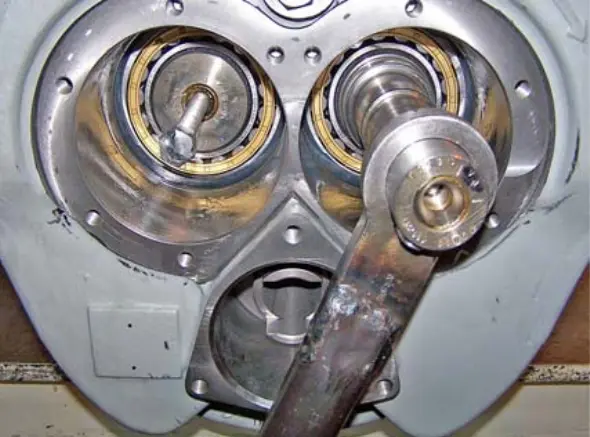 fig. 16. Rotor fixation fig. 16. Rotor fixation |
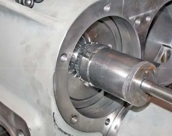 figure 17. Counternut figure 17. Counternut |
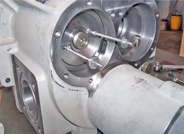 figure 18. Discharge drum figure 18. Discharge drum |
30. Remove the discharge drum bushing using extraction tools. Remove the o-rings and replace them when reassembling them.
31. Check the drum and bushing for wear and debris. Special attention should be paid to the sealing grooves on both elements. (Figure 19)
32. Loosen the mounting screws that secure the intake housing and remove the mounting pins that secure the intake case to the main crankcase. Check that there is no spring pressure on the unit. (Figure 20)
33. Support the intake end housing using a lifting tool. (Figure 39) and remove the mounting screws and washers.
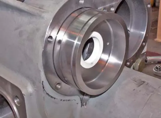 figure 19. Drum and bushing figure 19. Drum and bushing |
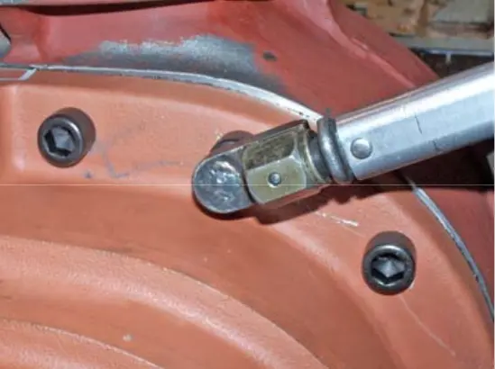 figure 20. Intake housing mounting screws figure 20. Intake housing mounting screws |
34. Remove the intake case. Make sure that the spool is supported when separating the crankcases.
NOTE: DO NOT STAND IN THE WAY OF THE SPOOL STOP. It is unlikely that it will be used when the intake crankcase is removed. The spool return spring may still be under compression. Try to release the spool stop by tapping it on the side with a soft mallet. Make sure the focus is protected in the event of an unexpected release.
35. Remove the spool stop. (Figure 21) and the return spring (Figure 22) and check both elements for wear and damage.
36. Remove the spool and check it for wear and damage on the protrusions and around the perimeter. (Figure 23)
37. Check the spool hole for wear, damage, and debris.
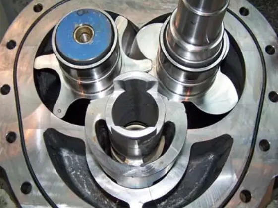 figure 21. Spool stop figure 21. Spool stop |
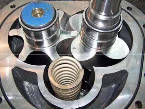 figure 22. Return spring figure 22. Return spring |
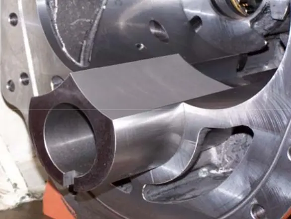 figure 23. Spool figure 23. Spool |
38. Prepare an area with either “supports” to support the rotor shafts after removing the rotors from the compressor crankcases, or a soft surface to place the rotors on it. This is necessary to avoid damaging the rotor tip seals.
39. Place the rotor lock on the compressor drive shaft to secure the rotors. (Figure 24)
40. Remove the discharge drum and the spacer lock pins from the inlet housing. (Figure 25)
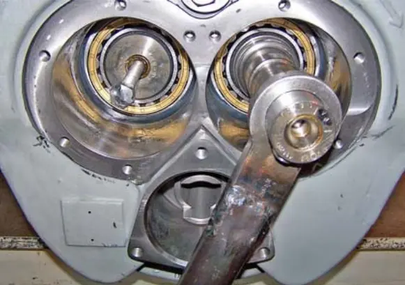 figure 24. Rotor fixation figure 24. Rotor fixation |
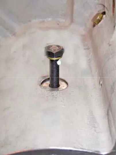 figure 25. Spacer lock pins figure 25. Spacer lock pins |
41. Disconnect the spring washer that secures the angular contact bearings to the “dad” rotor using a small punch and mallet. (Figure 26)
42. Remove the lock nut, preferably using a special tool. (Pic. 27) Before removing the rotors from the main crankcase, place the package under the cylinder to prevent tilting due to the center of gravity.
43. Place the rotor removal tool on the compressor outlet housing on the “dad” side and squeeze the rotor out of its thrust unit.
44. Repeat these steps when removing (subsections 4 or 6) the “mother” rotor.
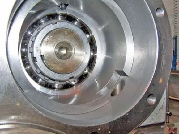 figure 26. Spring washer figure 26. Spring washer |
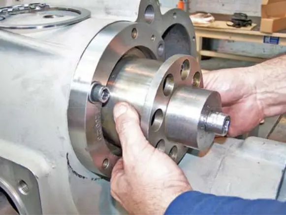 figure 27. Counternut figure 27. Counternut |
45. After releasing the rotors from the angular contact bearings, remove the “dad” rotor from the crankcase hole to a sufficient height to use the lifting tool to remove it from the crankcase. (The rotor's center of gravity is approximately at its midpoint)
46. Check the rotor for wear and scuffing, then set it aside in a prepared area.
47. Repeat these steps when removing the “mother” rotor.
48. Remove the angular contact bearing cartridges from the exhaust housing hole and remove the units. (Figure 28)
49. Using a tool to remove the treadmill cage or internal heating element, remove the inner roller bearing treadmills with the rotor shaft and discard them.
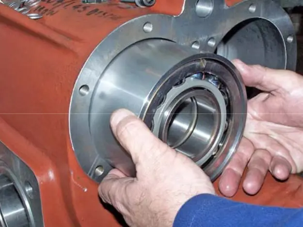 figure 28. Angular contact bearing cartridges
50. Remove the outer roller bearing rings and oil separator rings from the exhaust crankcase holes and discard the rings. (Figures 29, 30)
51. Remove and discard the disc springs from the bearing hole at the outlet end. (Figure 31)
52. Remove the clips, floating seals, and o-rings from the inlet end housing holes. (Figure 32)
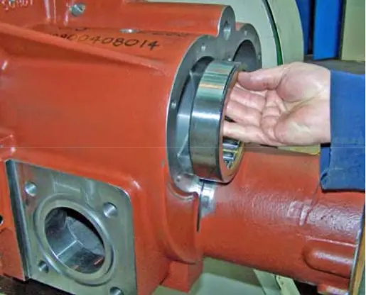 figure 29. Outer roller bearing ring figure 29. Outer roller bearing ring |
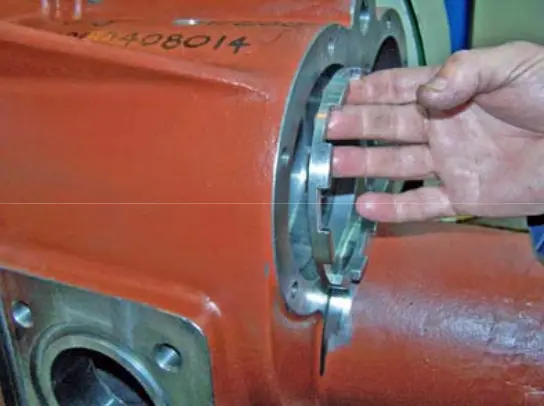 figure 30. Oil separating ring figure 30. Oil separating ring |
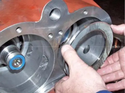 figure 31. Disc spring figure 31. Disc spring |
 figure 32. Retainer figure 32. Retainer |
53. Using the lock ring loops, remove the retaining rings and remove the bearing rings and o-rings from the holes. Discard the bearing rings and o-rings. (Figure 33)
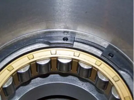 figure 33. Locking ring
54. Remove the inner lock ring that secures the indicator spindle bearing and remove the spindle/bearing assembly.
55. Remove the outer lock ring from the indicator spindle, remove and discard the bearing.
56. Remove and discard the O-ring from the hole in the drive cylinder cover.
57. Squeeze the labyrinth seal off the discharge drum bushing and discard it. (Figure 34)
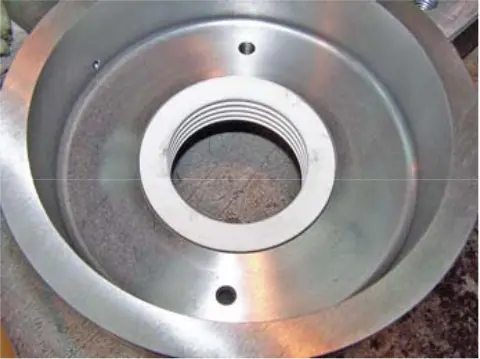 figure 34. Labyrinth discharge drum bushing seal
Howden compressors
Howden XRV127 Howden XRV163 Howden XRV204 Howden WRV163 Howden WRV204 Howden WrVi255 Howden WrVi321
Technical documentation for XRV 127 compressors
XRV 127 Description XRV 127 operation Dismantling XRV 127 Assembling XRV 127 XRV 127 tools XRV 127 Parts XRV 127 schemes
Technical documentation for XRV 163-204 compressors
xrv 163-204 Description xrv 163-204 operation Dismantling XRV 163-204 XRV 163-204 assembly XRV 163-204 tools XRV 163-204 Spare Parts XRV 163-204 schemes
Technical documentation for WRV compressors - WRVi
WRV description WRV operation WRV 163 repair WRV 204-255-321 repair WRV tools WRV spare parts WRV-WRVI diagrams