- En →
- Zapchasti Kompressorov →
- Kompressory Howden →
- Remont 204 255 321 Kompressora
Toros LLC is industrial cold of Europe
Spare parts, repair and maintenance of refrigeration units.
Spare parts for compressors in stock and on order!
call:
WhatsApp
e-mail: storopov86@gmail.com
Dismantling the WRV204, WRVi255, WRVi321 and WRVi365 compressor
for major repairs
GENERAL PROCEDURES
Although annual inspection and maintenance are recommended when condition monitoring equipment is not available, it is important to carry out major repairs after about 4 years of operation or earlier, depending on local conditions.
To carry out a major overhaul, do the following:
1. If necessary, isolate, reduce pressure, and empty the system.
2. Disconnect the drive and driven coupling halves.
3. Disconnect all gas and oil pipes attached to the compressor.
4. Remove the BSP conical plug” or 1" in size from the bottom of the inlet cover, collect the oil to drain.
5. Remove the gas inlet strainer.
6. Remove the mounting pins (if equipped) and the mounting bolts from the compressor legs.
7. Lift the compressor to a clean and dry place where disassembly and assembly will take place.
Disassembly and reassembly notes:
The method of disassembly and assembly varies slightly between the WRV163 compressor and the WRV204, WRVi255 and WRVi321 compressors due to design differences. It is therefore important to use the right procedure according to the size of the compressor.
You should always refer to the sectional layout that is supplied.
Use only appropriate lock nut wrenches to avoid damaging their slots.
Special tools can be supplied on request to speed up assembly and disassembly.
All spring washers, lock washers with legs, o-rings and teflon unit gaskets should be replaced.
All spring washers should be assembled according to the procedure.
All clips must be tightened with a certain torque.
DISASSEMBLING THE COMPRESSOR
The compressor should be disassembled according to the procedure in preparation for the annual inspection. Then proceed to the next step:
Support bearing clearance check (WRV204) - according to the procedure for WRV163.
Checking the support bearing clearance (WRVi255 and WRVi321 mm)
Loosen the control pins by securing the end cover of the thrust body so that it does not touch the outer rim of the thrust bearing. (Figures 53-54) This requires a slightly different method of measuring bearing lift, because there is no longer a hole at the end of the rotor into which the lever is inserted to lift the rotor. In this case, the limb indicator should be installed, but the end of the rotor must be raised or raised on the bottom of the stop fixing plate. The bearing clearance is equal to the specified value minus 0.001” (0.025 mm). Repeat the procedure on the other rotor. If you have any doubts about the bearing clearance, replace it. Because the bearings at the inlet end have a lighter load, they only need to be inspected for signs of wear on the bearings at the exhaust end.
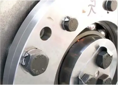 figure 53. Control pins figure 53. Control pins |
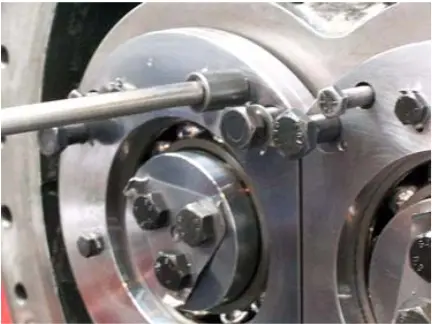 figure 54. Thrust body end cover figure 54. Thrust body end cover |
If checking the support bearing clearance reveals that the bearing's diametrical clearance is less than the maximum allowable value (see Fig. Pic. 55), you should consider the benefits of a longer service life with new support bearings before deciding to reuse existing bearings.
 figure 55. Bearing clearance table
Removing the intake shaft seal
After removing the driven coupling half and the cotter pin, remove the mounting screws from the shaft end cover and, using the existing lifting holes and T-shaped lifting tools, remove the shaft cover. (Fig.56)
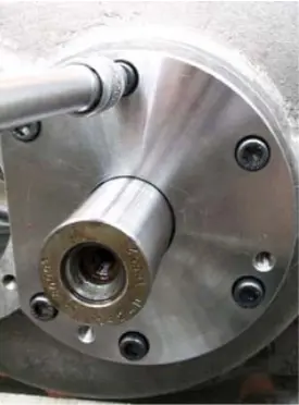 figure 56. Shaft cover
Remove the shaft seal, taking care not to damage the graphite seal surface (Figure 57). Remove the inlet discharge drum using T-shaped lifting tools in the existing lifting holes (Figure 58). Complete these steps by removing the fixed seat from the seal cover.
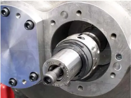 figure 57. Shaft seal figure 57. Shaft seal |
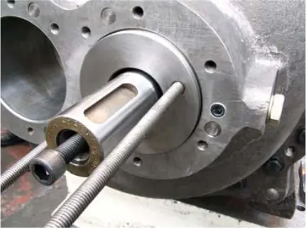 figure 58. Inlet discharge drum figure 58. Inlet discharge drum |
Removing the Vi controller
Remove the fixing clip at the back of the square Vi adjusting screw and insert the adjusting screw into the compressor. Remove the mounting screws that secure the Vi cover and remove the cover.
Removing the inlet end cover (Figure 59)
Place the eye bolt at the top of the intake cover on the main crankcase. (Figure 59) Remove the mounting pins that secure the intake cover to the main crankcase.
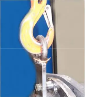 figure 59. Eye bolt on the inlet end cover figure 59. Eye bolt on the inlet end cover |
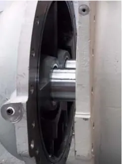 figure 60. Inlet cover figure 60. Inlet cover |
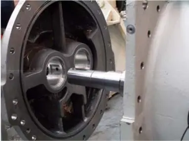 figure 61. Main crankcase intake cover figure 61. Main crankcase intake cover |
Remove the remaining control pins and gently slide the intake cover over the extended rotor shaft “dad” along with the o-ring. (Figures 60-61)
Removing rotors
When preparing to remove the rotors, disconnect the thrust bearing spring washer (Pic. 62) and remove the lock nuts from the male and female rotors (Pic 63).
The structural difference between the above mentioned compressors and the WRV163 and WRV204 compressors is that the thrust bearing housings are installed in the WRVi255, WRVi321 and WRVi365 compressors.
Before removing the rotors, remove the thrust bearings. It is known that thrust housings with lifting removal holes are used as means of removing bearings by lifting the housings and removing the bearings from them. It is not recommended to use this method of removing the thrust bearing. The thrust housing flange may be deformed due to the strong tightening of the thrust bearing. This will have a negative effect on the exhaust end clearance. The right procedure is:
1. Remove the installation screws that secure the thrust housing to the main crankcase. Install three long rods and a jack support.
2. Using a suitable hydraulic jack and cylinder between the jack support and the end of the rotor shaft, press the cylinder with a pump, remove each rotor one by one from the thrust bearings and crankcases. (Figure 64)
3. Gently support the rotors according to the scheme (Figure 65-66).
4. The weights of rotors of various sizes are shown in the following table (Figure 67).
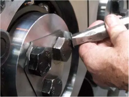 figure 62. Thrust bearing spring washer figure 62. Thrust bearing spring washer |
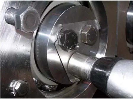 figure 63. Counternuts figure 63. Counternuts |
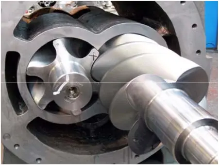 figure 64. Rotors figure 64. Rotors |
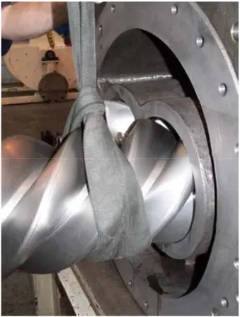 figure 65. Removing the rotor figure 65. Removing the rotor |
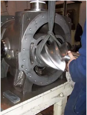 figure 66. Removing the rotor figure 66. Removing the rotor |
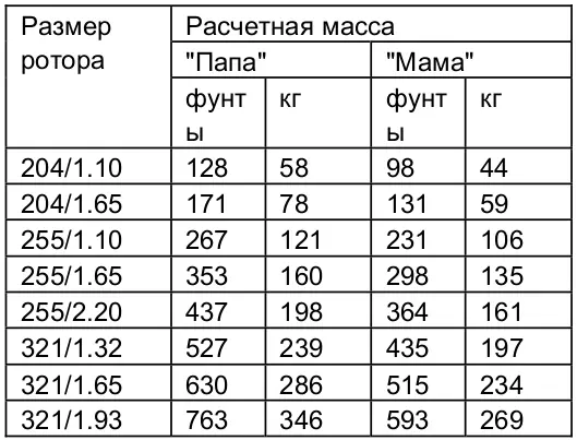 figure 67. Calculated rotor weight table figure 67. Calculated rotor weight table |
It is now easy to remove thrust bearing bushings and angular contact bearings. It is now easy to access the discharge drum and discharge drum bushing, as well as remove the drums and bushings using threaded T-profiles (see List of special tools).
The support bearings are fixed in the intake case with locking rings and fastened with mounting pins. After removing the retaining ring, you can squeeze out the bearing and remove it using a special tool specified in the catalogue. The bearings at the outlet end are fixed with a stop plate secured with mounting screws. After removing the fixing plate, the support bearing is removed in the same way as the bearing at the inlet end. When preparing for reassembly, install new bearings.
COMPRESSOR ASSEMBLY
After the repair or adjustment is complete, reassemble the compressor as follows:
1. Lubricate the bearing holes with lubricating oil and lift them into the rotors; check that the blades match the serial numbers on the rotors.
2. Assemble the intake case on the main crankcase, place the mounting pins, install the bolts and tighten them (according to the torque characteristics).
3. Assemble the discharge drum bushings in the crankcase at the exhaust end, install the discharge drums, and then the thrust bearing bushings. Check that the adjusting elements are located between the support bush flange and the main crankcase.
4. Heat the angular contact bearings in an oil bath at about 100°C and assemble them on the rotors.
5. Secure the spring washers and lock nuts (Figure 63).
6. Torque - according to specifications.
Angular contact bearings are designed only for axial support. The thrust bearing does not tighten tightly on the outer diameter in the thrust housing. In this case, it is necessary to clamp the outer ring of the bearing to prevent it from rotating with the rotor. To do this, the jack support must be secured to fit on the outer ring of the bearings. The required fit is listed in the table below. (Figure 68)
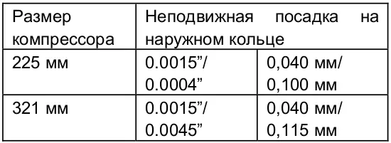 figure 68. Planting table figure 68. Planting table |
 figure 69. Gap check figure 69. Gap check |
At this stage of assembly, the rotor end gap should be checked to ensure that its value is correct. (fig. 69)
Checking the rotor exhaust gap
For WRV204 compressors, see the procedure for WRV163. For the WRVi255, WRVi321 and WRVi365 compressors, loosen the installation screws that secure the thrust bearing housing to the main crankcase. Don't take them off.
Insert the lifting screws into the holes on the bearing housing flange and tighten them slightly until you feel resistance.
The tension of the lifting screws leads to the removal of rotors on the outlet surface of the main crankcase.
Place the limb indicator on a convenient part of the main crankcase, with the indicator spindle touching the end of the rotor (Figure 71). Stop tensioning the lifting screws and loosen them for a few turns.
Set the limb indicator to zero.
Use a wrench to tighten the mounting screws that secure the bearing housing to the main crankcase and tighten the screws to the specified torque value.
NOTE: The movement shown on the indicator scale is the gap at the exhaust end of the rotor. Compare it with the value in the table in Figure 70.
 figure 70. Rotor Exhaust End Gap Table
Adjustment, if necessary, is performed by machining the adjusting discs behind the bearing thrust bushing. (WRVi255 and WRVi321) The exhaust end of the WRV204 compressor rotor is cleared by grinding the male and female discharge drums. (Fig.72)
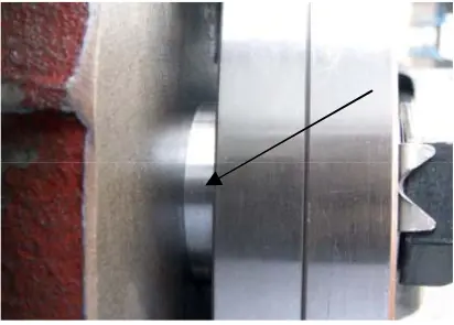 figure 71. Indicator spindle figure 71. Indicator spindle |
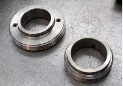 figure 72. “dad” and “mom” discharge drums figure 72. “dad” and “mom” discharge drums |
Reassembling the exhaust end cover and hydraulic cylinder
Reassemble the WRV204, WRVi255, WRVi321, and WRVi365 compressors. Then follow these steps:
Reassembling the Vi cover
Pull the Vi adjusting screw until the nut is attached to the intake cover. Reinstall the Vi controller cover, making sure that the new o-rings are installed, and tighten the mounting screws. Replace the fixing ring to secure the adjusting screw to the cover.
Reassembling the intake shaft seal
Reassemble the component in the following sequence:
1. Insert the inlet discharge drum, making sure that it is located on the drive pin.
2. Lubricate the shaft seal and assemble the rotor shaft, install the pin pointing outward/inlet drum pin.
3. Reinstall the discharge drum bushing (WRV204 only).
4. Place the new O-ring on the fixed seat and insert the seals into the cover; the seat must be on the lock pin.
5. Install the seal cover with the new O-ring and secure it with mounting screws, tightening them systematically to avoid tilting.
To complete the assembly, install the clutch pin and the compressor clutch half.
Howden compressors
Howden XRV127 Howden XRV163 Howden XRV204 Howden WRV163 Howden WRV204 Howden WrVi255 Howden WrVi321
Technical documentation for XRV 127 compressors
XRV 127 Description XRV 127 operation Dismantling XRV 127 Assembling XRV 127 XRV 127 tools XRV 127 Parts XRV 127 schemes
Technical documentation for XRV 163-204 compressors
xrv 163-204 Description xrv 163-204 operation Dismantling XRV 163-204 XRV 163-204 assembly XRV 163-204 tools XRV 163-204 Spare Parts XRV 163-204 schemes
Technical documentation for WRV compressors - WRVi
WRV description WRV operation WRV 163 repair WRV 204-255-321 repair WRV tools WRV spare parts WRV-WRVI diagrams