- En →
- Zapchasti Kompressorov →
- Kompressory Howden →
- Remont Wrv163 Kompressora
Toros LLC is industrial cold of Europe
Spare parts, repair and maintenance of refrigeration units.
Spare parts for compressors in stock and on order!
call:
WhatsApp
e-mail: storopov86@gmail.com
DISASSEMBLING THE WRV163 COMPRESSOR FOR OVERHAUL
GENERAL PROCEDURES
Although annual inspection and maintenance are recommended when condition monitoring equipment is not available, it is important to carry out major repairs after about 4 years of operation or earlier, depending on local conditions.
To carry out a major overhaul, do the following:
1. If necessary, isolate, reduce pressure, and empty the system.
2. Disconnect the drive and driven coupling halves.
3. Disconnect all gas and oil pipes attached to the compressor.
4. Remove the BSP conical plug” or 1" in size from the bottom of the inlet cover, collect the oil to drain.
5. Remove the gas inlet strainer.
6. Remove the mounting pins (if equipped) and the mounting bolts from the compressor legs.
7. Lift the compressor to a clean and dry place where disassembly and assembly will take place.
Disassembly and reassembly notes:
The method of disassembly and assembly varies slightly between the WRV163 compressor and the WRV204, WRVi255 and WRVi321 compressors due to design differences. It is therefore important to use the right procedure according to the size of the compressor.
You should always refer to the sectional layout that is supplied.
Use only appropriate lock nut wrenches to avoid damaging their slots.
Special tools can be supplied on request to speed up assembly and disassembly.
All spring washers, lock washers with legs, o-rings and teflon unit gaskets should be replaced.
All spring washers should be assembled according to the procedure.
All clips must be tightened with a certain torque.
DISASSEMBLING THE COMPRESSOR
The compressor should be disassembled according to procedures in preparation for the annual inspection. Then proceed to the next step:
Checking the support bearing clearance (163 mm)
At this stage of disassembly, check the support bearing clearance to determine whether the support bearings need to be replaced during compressor repairs.
Check that the stop fixing plate has been removed from the model 163. (Figure 1 -2)
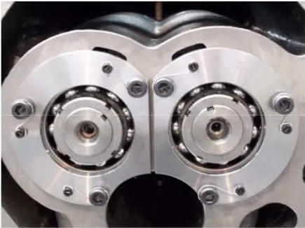 fig. 1. Thrust fixing plate fig. 1. Thrust fixing plate |
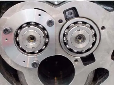 fig. 2. Remove the stop fixing plate fig. 2. Remove the stop fixing plate |
Ensure a round rod with a diameter of 1⁄2” (13 mm) and approximately 14” (384 mm) in length. Place the limb indicator in a convenient position on the main crankcase so that the limb indicator spindle lies on the rotor or rotor lock nut.
Set the limb indicator to zero.
Insert a short section of the rod into the hole at the end of the rotor shaft. When raising and lowering the rod, you can consider the reading on the indicator with a limb. This reading indicates that the shaft is rising. By subtracting 0.001” (0.025 mm) from this reading due to the lift angle, it is possible to obtain the bearing clearance value. Compare this figure to the table of bearing clearance values in Figure 3.
 fig. 3. Table of bearing clearance values
Repeat the procedure on both rotors. If you have any doubts about the bearing clearance, replace it.
Since the bearings at the inlet end have a lighter load, they only need to be inspected to see if the bearings at the exhaust end need to be replaced.
Disassemble by disconnecting the spring washers and lock nuts that secure the thrust bearings (Pics. 4 to 5) and remove them. The adjusting ring behind the thrust bearing has marked stretch marks that allow the ring to be removed using lifting screws; when the adjusting ring is removed, the thrust bearing is removed. (Figures 6-7)
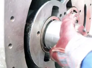 fig. 4. Spring washer and lock nut fig. 4. Spring washer and lock nut |
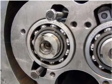 fig. 5. Thrust bearings fig. 5. Thrust bearings |
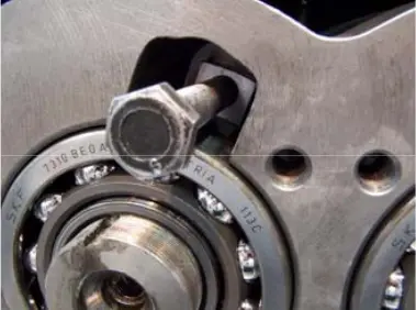 figure 6. Thrust bearing figure 6. Thrust bearing |
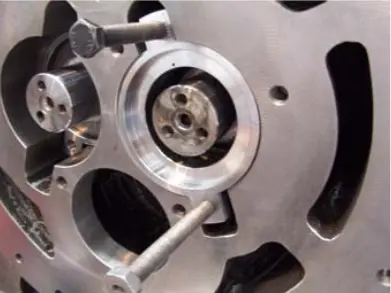 figure 7. Adjusting ring figure 7. Adjusting ring |
Removing the intake shaft seal (163 mm)
Remove the driven clutch pin from the intake shaft. Remove the mounting screws (Figure 8) from the shaft seal cover and use the lifting screw holes at the connection to the T-shaped lifting tools to remove the shaft seal cover. Then remove the intake shaft seal unit (Pics. 9 - 10), i.e. the fixed part with the sealing ring, the shaft seal and the discharge drum/labyrinth seal. There are lifting holes for removing the discharge drum using T-shaped tools.
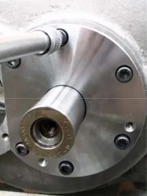 figure 8. Shaft seal cover mounting screws figure 8. Shaft seal cover mounting screws |
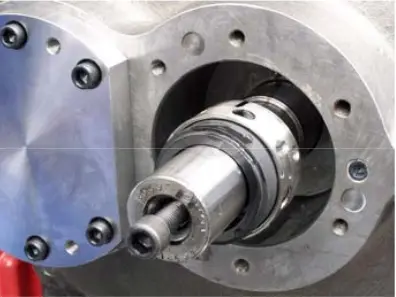 fig. 9. Shaft seal fig. 9. Shaft seal |
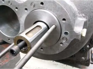 fig. 10. Discharge drum/labyrinth seal fig. 10. Discharge drum/labyrinth seal |
Removing the inlet end cover (WRV 163 mm)
Insert the eye bolt into the screw hole at the top of the intake cover flange.
Attach the belt to the eye bolt and support the lid mass with a lifting tool. (Figure 11)
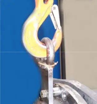 figure 11. Eye bolt figure 11. Eye bolt |
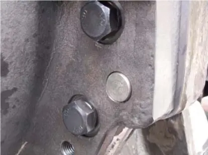 fig. 12. Inlet cover mounting screws/mounting pins fig. 12. Inlet cover mounting screws/mounting pins |
Remove most of the screws that secure the intake cover to the main crankcase. Remove the mounting pins that secure the intake cover to the main crankcase (Figure 12). Remove the remaining screws and gently slide the intake cover over the extended rotor shaft “dad” along with the o-ring, taking extreme care to avoid damaging the inlet end support bearings located in the inlet end cover (Figure 13).
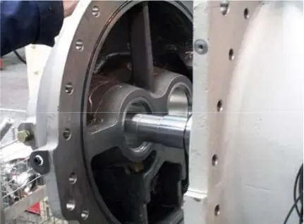 figure 13. Inlet cover
Removing rotors (163 mm)
Now, after removing the inlet and outlet crankcases and thrust bearings, as described earlier, it is possible to remove the rotors from the main crankcase, as shown in Pics. 14-15. See the estimated rotor weight in the table in Figure 16.
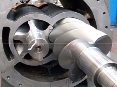 figure 14. Rotors figure 14. Rotors |
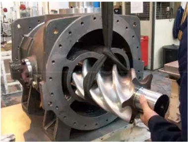 fig. 15. Removing the rotor fig. 15. Removing the rotor |
 fig. 16. Calculated rotor weight table
It is now possible to remove the support bearings from the main and intake crankcases using a extraction tool. See the list of tools.
Install new support bearings using an assembly tool.
The support bearings are fixed with a mounting pin and fastened with locking rings.
REASSEMBLING THE WRV163 COMPRESSOR AFTER MAJOR REPAIRS
After the repair or adjustment is complete, reassemble the compressor as follows:
1. Lubricate the support bearing holes with clean lubricating oil.
2. Raise the rotors to their position in the crankcase holes, check that the blades match the serial numbers printed on the rotors.
3. Assemble the intake case on the main crankcase, attach the mounting pins, and secure with control pins.
4. Remove the mounting loop.
5. Place the thrust bearing adjustment plates on the rotor shafts at the exhaust end and insert them into place, then insert the angular contact bearings. Angular contact bearings can be heated in an oil bath to about 100°C before installation and compressed using a special tool. Before replacing the wire securing the stop fixing plate, it is necessary to check that the end of the rotor outlet end is correct.
6. Install the spring shack/lock nut and secure it. (Figure 4)
Rotor exhaust gap check (163 mm)
1. Remove the stop fixing plate (if installed).
2. The adjusting plate behind the thrust bearings has two eyelets with threaded holes for extraction.
3. Insert the lifting screws into the eyelets and pull them slightly until you feel resistance. (Figure 17)
4. The tension of the screws causes the rotors to be removed at the exhaust end of the main crankcase.
5. Place the clock indicator in a suitable place in the crankcase, with the indicator spindle touching the end of the rotor.
6. Replace the stop plate and the mounting screws. (Figure 1-2)
7. Stop tensioning the lifting screws (Fig.18).
8. Set the clock indicator to zero.
9. Tighten the plate mounting screws with a wrench to a torque of up to 14 Nm.
10. Watch the indicator's movement. This is the gap at the exhaust end of the rotor and it must match the table shown in figure 19.
11. Adjustment, if necessary, is performed by machining the thrust bearing extraction plates.
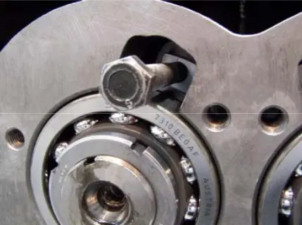 figure 17. Lifting screw figure 17. Lifting screw |
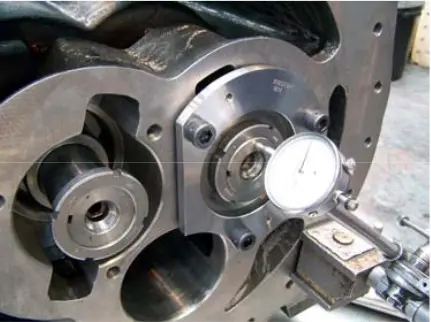 figure 18. Indicator figure 18. Indicator |
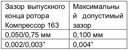 figure 19. Rotor Exhaust End Gap TableAfter the gaps are finally installed, the mounting screws on the stop fixing plate must be fixed with wire in the following way: Wire class used: 1/16” in diameter. Annealed S.S. Control wire Adjustment, if necessary, is performed by machining the adjusting plate behind the thrust bearings. (Figure 20)
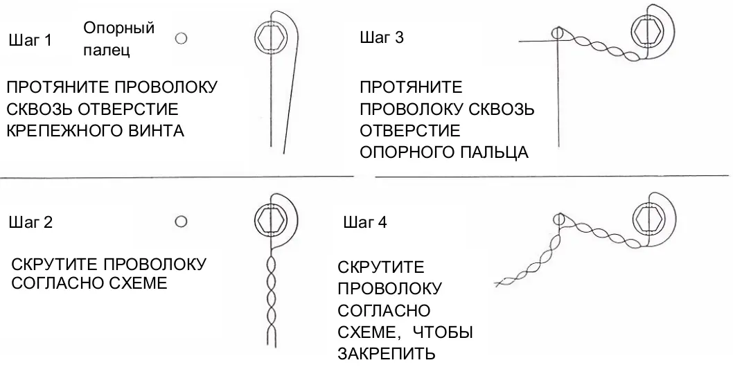 figure 20. Wire fixing scheme for mounting screws
Reassemble the combined cap/exhaust cylinder (163 mm)
Reassemble as described in section 7.5 for compressor 163, then follow these steps:
Reassembling the intake shaft seal (163 mm)
Reassemble the components in the following sequence:
1. Assemble the discharge drum on the rotor shaft, securing the pin with the handguard pointing outward.
2. Lubricate the shaft seal and assemble the rotor shaft, install the pin pointing outward/discharge drum pin.
3. Assemble the fixed part with the o-ring mounted on the outer diameter recess.
4. Install the seal body with the new O-ring and secure it with mounting screws, tightening them systematically to avoid tilting.
The torque of the mounting screws is 35 lbf (48 Nm).
To complete the assembly, install the clutch pin and the compressor clutch half.
Howden compressors
Howden XRV127 Howden XRV163 Howden XRV204 Howden WRV163 Howden WRV204 Howden WrVi255 Howden WrVi321
Technical documentation for XRV 127 compressors
XRV 127 Description XRV 127 operation Dismantling XRV 127 Assembling XRV 127 XRV 127 tools XRV 127 Parts XRV 127 schemes
Technical documentation for XRV 163-204 compressors
xrv 163-204 Description xrv 163-204 operation Dismantling XRV 163-204 XRV 163-204 assembly XRV 163-204 tools XRV 163-204 Spare Parts XRV 163-204 schemes
Technical documentation for WRV compressors - WRVi
WRV description WRV operation WRV 163 repair WRV 204-255-321 repair WRV tools WRV spare parts WRV-WRVI diagrams