- En →
- Zapchasti Kompressorov →
- Kompressory Howden →
- Sborka Xrv127 Kompressora
Toros LLC is industrial cold of Europe
Spare parts, repair and maintenance of refrigeration units.
Spare parts for compressors in stock and on order!
call:
WhatsApp
e-mail: storopov86@gmail.com
Assembling the XRV 127 compressor during overhaul
Compressor assembly procedure. Part 1.
Intake shaft, gear cover and gear
1. Apply a protective film to the shaft sealing area.
2. Heat both angular contact bearings on a suitable induction heater to 80°C to 90°C and apply an anti-shock agent to the intake shaft (Figure 74).
3. Place the bearings on the intake shaft liner. Based on the assembly drawing, check that they are located with the back walls to each other (Figure 75).
4. Using the XR12009J pre-loaded bearing assembly tool, check that the bearings have fully occupied their space near the intake shaft liner.
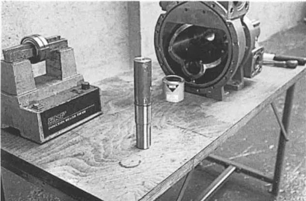 figure 74. Inlet shaft figure 74. Inlet shaft |
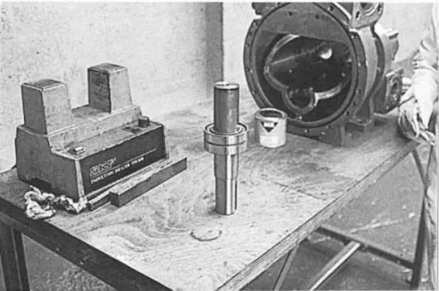 figure 75. Bearings figure 75. Bearings |
5. Then, assemble the shaft and bearing assembly in the gearbox cover (Figure 76) together with the seal housing (Figure 77).
NOTE: There is no need to install O-rings or shaft seals at this stage.
Gear
6. Support the gearbox cover horizontally with the intake shaft pointing down and place the gear bush on the shaft.
7. Heat the gear to a temperature of 80°C - 90°C and apply an anti-scuff compound to the shaft. (Figure 78) Put the gear on the shaft. (Figure 79)
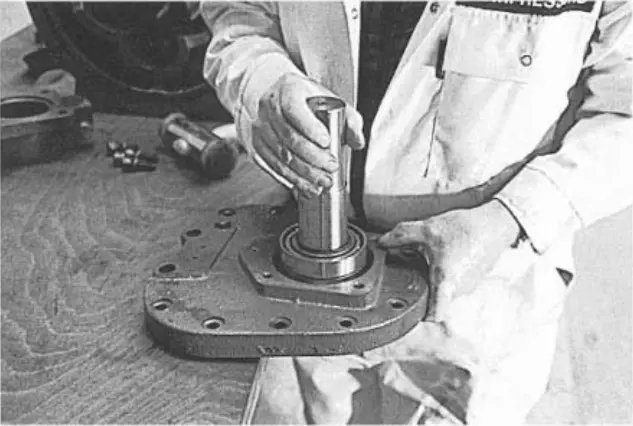 figure 76. Shaft and bearing unit in the gearbox cover figure 76. Shaft and bearing unit in the gearbox cover |
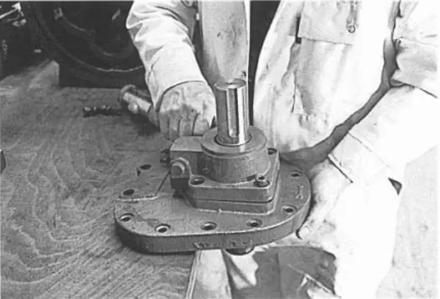 figure 77. Sealing body figure 77. Sealing body |
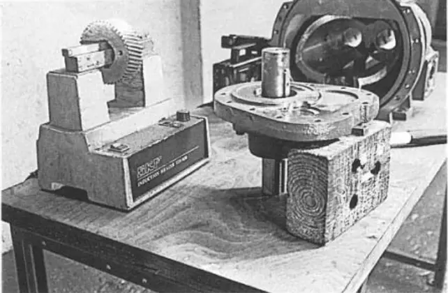 figure 78. Apply a decongestant figure 78. Apply a decongestant |
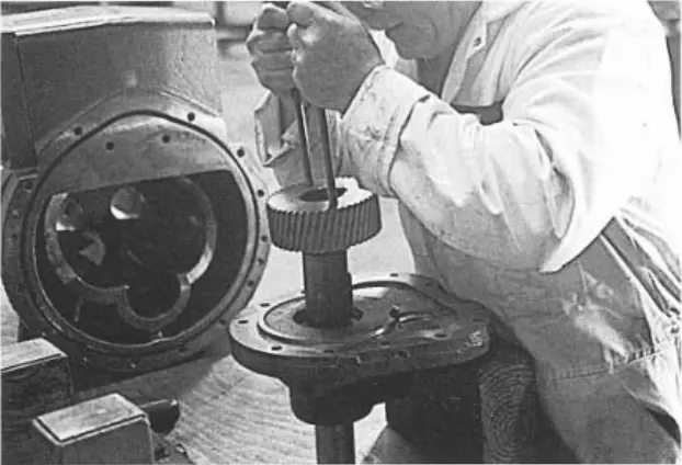 figure 79. Gear figure 79. Gear |
Inlet shaft spacer, cylindrical roller bearing inner ring and fixing shack/mounting screw
8. Heat the inlet shaft spacer and the inner ring of the cylindrical roller bearing to a temperature of 80°C - 90°C, apply an anti-shock compound to the shaft. (Figure 80)
9. Put the spacer (Figure 81) and then the inner ring of the cylindrical roller bearing in place. (Figure 82)
10. Check that all components on the shaft between the retaining ring and the inner ring of the roller bearing fit closely together. The shaft end should be just below the inner ring of the cylindrical roller bearing. Use Loctite 243 to place the bearing washer and mounting screw on the shaft end and tighten to 20 Nm. (Figure 83)
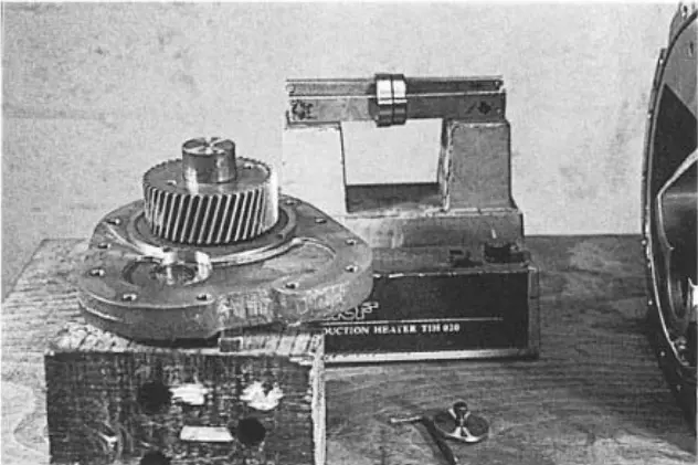 figure 80. Apply an anti-scuffing compound to the shaft figure 80. Apply an anti-scuffing compound to the shaft |
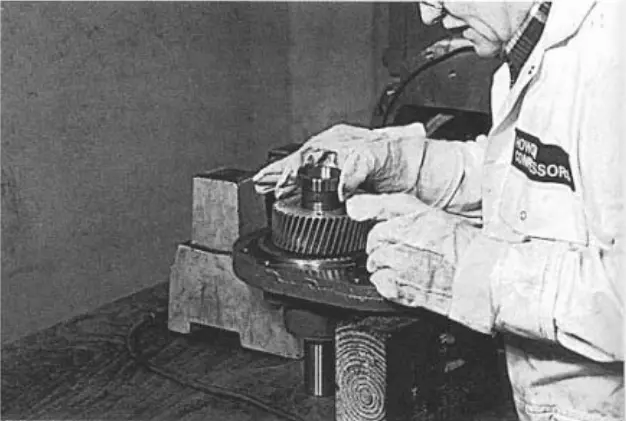 figure 81. Spacer figure 81. Spacer |
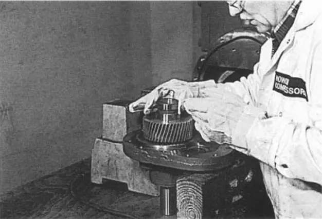 figure 82. Cylindrical roller bearing inner ring figure 82. Cylindrical roller bearing inner ring |
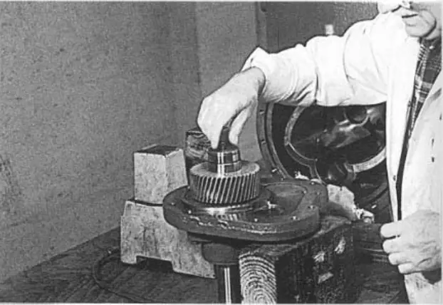 figure 83. Washer and mounting screw figure 83. Washer and mounting screw |
Check the preload of the bearing by pressing your hand on the shaft. If there is excessive movement, the bearing has not received the required preload. Correct as follows: (0.15 radially max, 0.1 axis max)
Remove the M8 mounting screw and the washer from the drive end and replace the washer with a thicker one (approximately 2 times thicker). Install a longer mounting screw and tighten to 20 Nm. (Figure 1a)
When the shaft is upright and the drive end is located on a flat “safe” surface, hit the pipe hard around the perimeter of the thick washer.
Re-tighten mounting screw up to 20 Nm.
Repeat this shock and tightening sequence until the mounting screw is fully secured.
If axial and radial travel are acceptable, replace the shaft body using an original washer and a mounting screw tightened to 20 Nm.
Spool
11. Check that the drive spindle guide pin is in place. (Figure 84) (Only installed on compressors with switches)
12. When installing the spool (Figure 85/86) in the main crankcase, we recommend that you push it completely through the outlet (Figure 87) as a test to make sure that it does not stick.
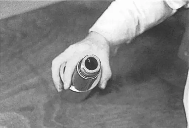 figure 84. Drive spindle guide pin figure 84. Drive spindle guide pin |
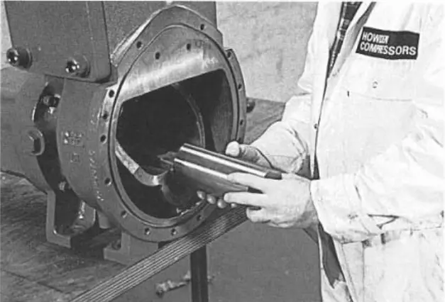 figure 85. Spool figure 85. Spool |
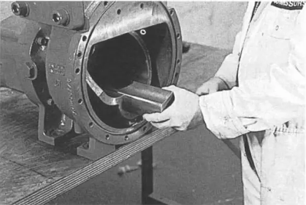 figure 86. Spool figure 86. Spool |
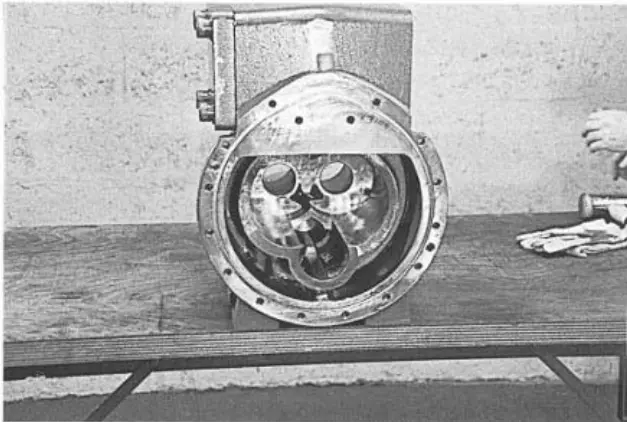 figure 87. Exhaust channel figure 87. Exhaust channel |
Rotor bearing spacer “female” and intermediate bearing
13. Lubricate and insert the XR12002J intermediate bearing into the output casing to simulate angular contact and cylindrical bearings. (Figure 88) Leave the intermediate bearing in place.
14. Put the “mom” bearing spacer on its shaft. Lubricate the rotor and carefully replace it in the main crankcase. (Figure 89) It is usually easier to install the “mother” rotor first.
NOTE: The “male” and “female” bearing spacers are used to set the gap at the exhaust end of the rotor.
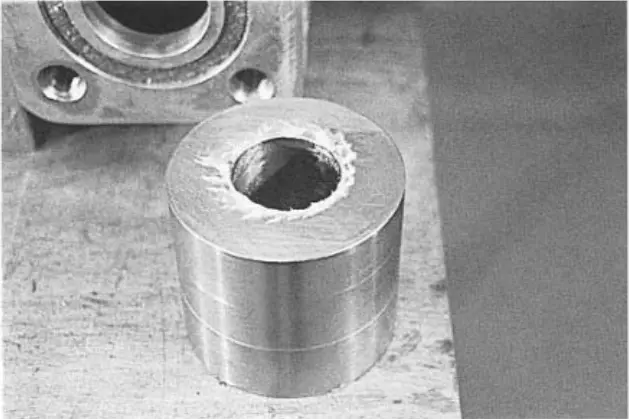 figure 88. XR12002J Intermediate Bearing figure 88. XR12002J Intermediate Bearing |
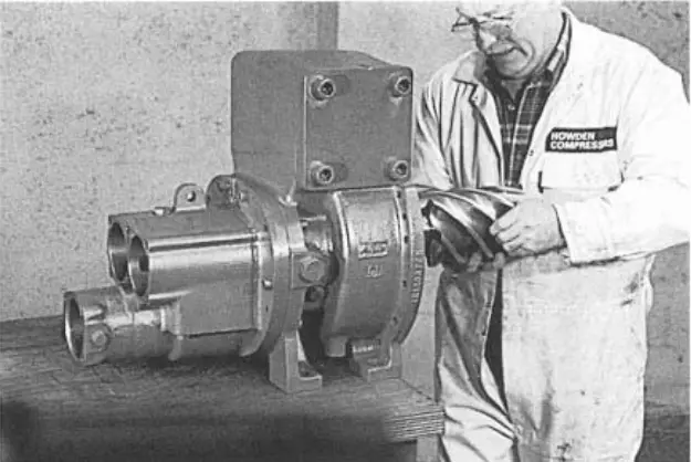 figure 89. Rotor figure 89. Rotor |
Rotor bearing spacer “male” and intermediate bearing
15. Place the “dad” bearing spacer on the “dad” shaft. (Figures 91 and 92)
16. Lubricate and place the “dad” intermediate bearing in the outlet casing. (Figure 93) Leave the intermediate bearing in place.
17. Turn the “dad” rotor to connect it to the “mom” rotor and push it through the body. (Figure 94)
Check that the rotor serial numbers match. Please note that some rotor blades do not have serial numbers.
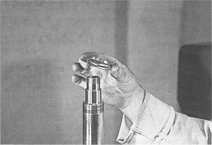 figure 91. Bearing spacer figure 91. Bearing spacer |
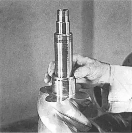 figure 92. Bearing spacer on the shaft figure 92. Bearing spacer on the shaft |
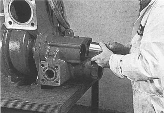 figure 93. Output cover figure 93. Output cover |
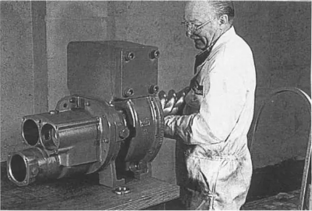 figure 94. Rotor figure 94. Rotor |
Assembly - attaching the gearbox to the main crankcase
18. The reducer is installed together with the outer ring of the cylindrical roller bearing of the rotor “male” and “mother”, as well as together with the spool stop.
Keep the gearbox mass in a raised position (Figure 95) and carefully place the gearbox on the main crankcase. (Figure 96)
NOTE: At this stage, it is not necessary to install a drive spring.
19. Secure the gearbox with several M12 slotted mounting screws and push the gearbox mounting pins into place to ensure that the crankcases fit correctly.
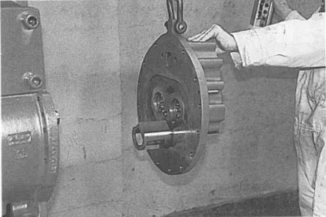 figure 95. Reducer figure 95. Reducer |
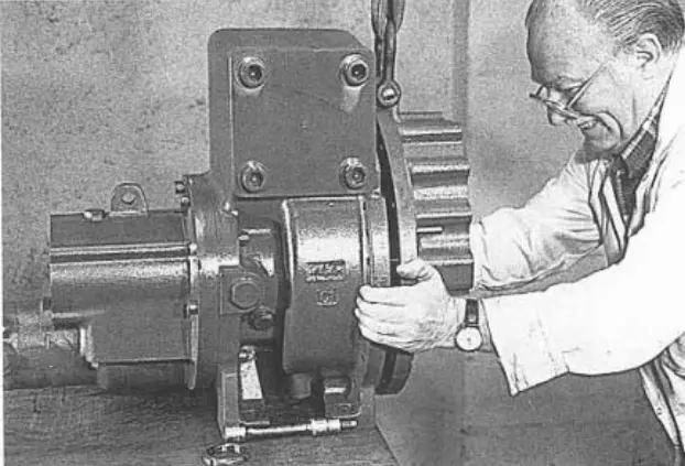 figure 96. Main crankcase reducer figure 96. Main crankcase reducer |
Determination of the total rotor clearance (0.725 max. - 0.325 min)
20. Set the limb indicator to zero at the inlet end of each rotor one by one. (Figure 97) Move the rotor axially along its entire length; the indicator will show the overall gap between the rotor end and the crankcase.
21. Repeat the same procedure with the other rotor.
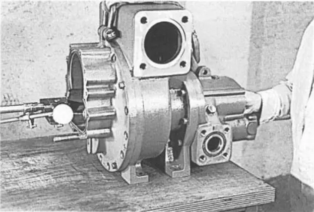 figure 97. Indicator at the inlet end of the rotor figure 97. Indicator at the inlet end of the rotor |
|
The gap between the end of the rotor and the exhaust end of the crankcase (0.090 max. - 0.065 min.)
22. Replace the “male” rotor lock nut (Figure 99) and tighten to 200 Nm. (Figure 100)
23. Do the same with the “mom” rotor lock nut.
NOTE: The torque applied must match the final assembly torque to ensure correct clearance readings.
24. Set the limb indicator to zero at the inlet end of the “dad” rotor. (Figure 101) Move the rotor along the axis. (Figure 102)
The axial motion marked on the indicator shows the gap between the “dad” rotor end and the crankcase exhaust end.
25. Repeat the same procedure with the “mom” rotor.
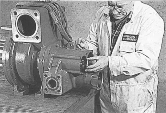 figure 99. Rotor lock nut figure 99. Rotor lock nut |
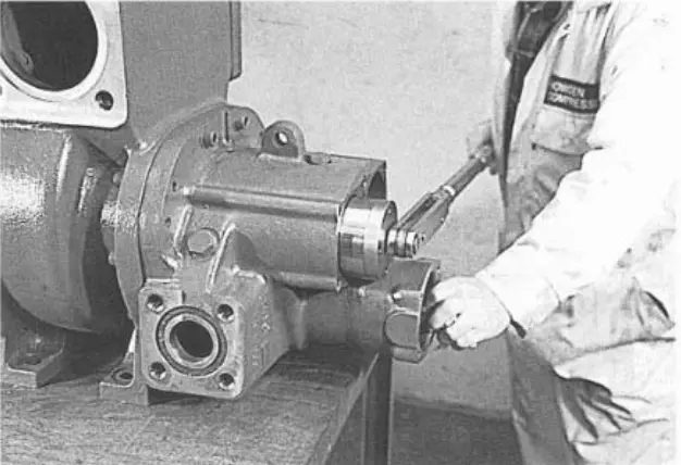 fig. 100. Counternut tightening fig. 100. Counternut tightening |
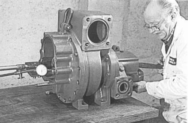 figure 101. Indicator at the inlet end of the rotor figure 101. Indicator at the inlet end of the rotor |
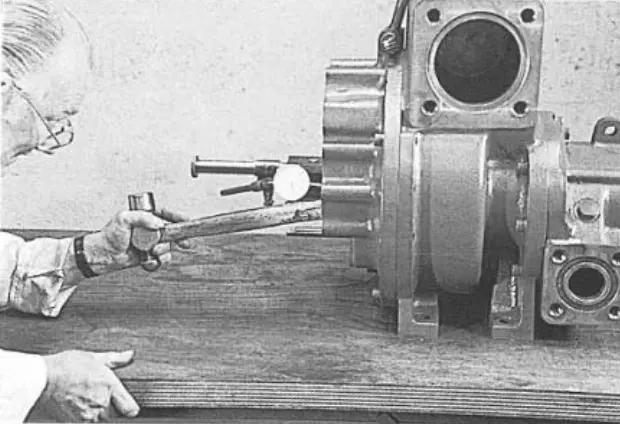 figure 102. Rotor displacement along the axis figure 102. Rotor displacement along the axis |
Removing the intermediate bearing
26. The intermediate bearings are removed (Figure 103) together with the attached bearing spacer (Figure 104) for lubrication.
27. You can now make any changes to the recorded gaps by sanding these spacers.
Once the correct clearances have been reached, the final assembly can begin.
Remove the gearbox and rotors, following the disassembly procedures.
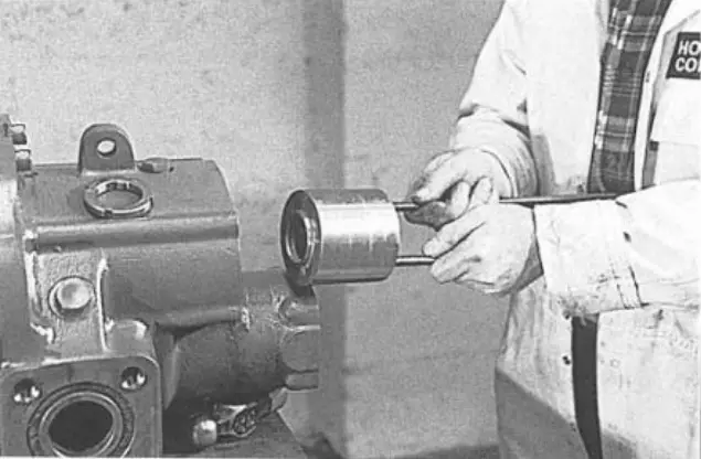 figure 103. Intermediate bearings figure 103. Intermediate bearings |
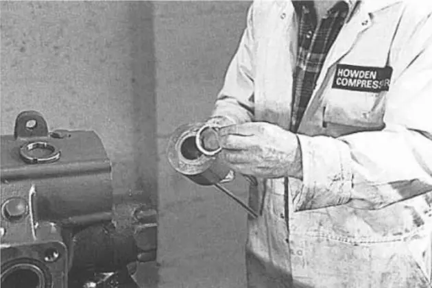 figure 104. Bearing spacer figure 104. Bearing spacer |
Installing a cylindrical roller bearing on the “dad” rotor
1. Heat the inner ring of the “male” cylindrical roller bearing on the induction heater to 80°C - 90°C and cover the rotor shaft with an anti-jamming compound. (Figure 105)
2. Put the ring on the shaft. (Figure 106)
Load 20 kg so that the inner ring is firmly in place. (Figure 107)
Do not remove until the parts have cooled down.
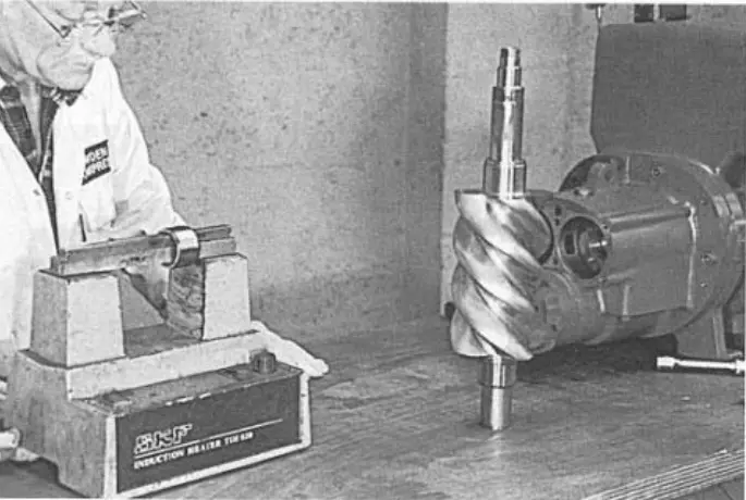 figure 105. Inner ring of the cylindrical roller bearing “male” figure 105. Inner ring of the cylindrical roller bearing “male” |
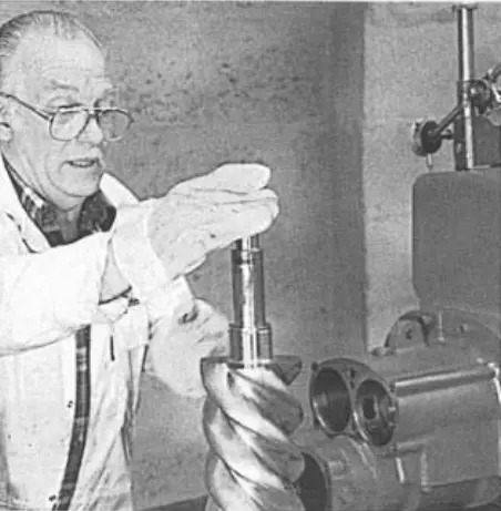 figure 106. Put the ring on the shaft figure 106. Put the ring on the shaft |
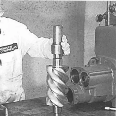 figure 107. Fitting the ring on the shaft figure 107. Fitting the ring on the shaft |
Floating hub “dad”
3. Check that both the O-ring and the mounting pin are correctly installed and insert them into the side of the outlet cover. (Figure 108)
Installing a cylindrical roller bearing “male” in the output casing
4. Insert the outer ring of the cylindrical roller bearing “male” and bearings. (Figure 109)
5. Insert the daddy intermediate bearing so that the bearing and floating bushing are in the correct position. (Figure 110)
Do not touch until the “dad” rotor is installed.
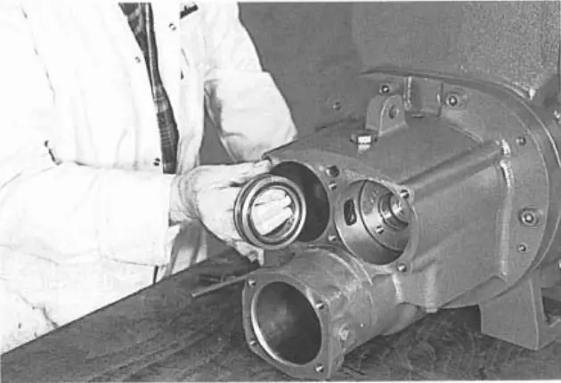 figure 108. Cylindrical roller bearing outer ring figure 108. Cylindrical roller bearing outer ring |
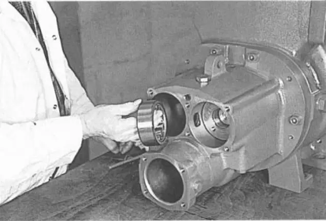 figure 109. Intermediate bearing figure 109. Intermediate bearing |
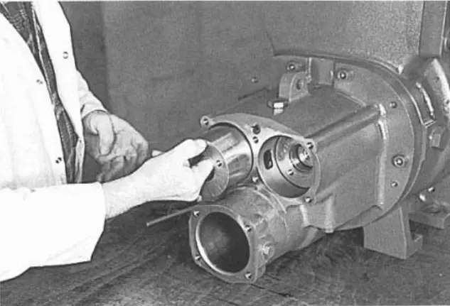 figure 110. Floating bushing figure 110. Floating bushing |
Floating “mother” bushing
6. Place the inner treadmill of the “female” cylindrical roller bearing on the rotor, following the procedure for installing the “dad” cylindrical roller bearing treadmill.
7. Lubricate and install the o-ring and the locking pin into the floating “mother” bushing (Figure 111), align the pin with respect to the opening of the outlet casing. (Figure 112)
8. Insert the outer ring of the “female” cylindrical roller bearing and the bearings. (Figure 113)
9. Insert the “female” intermediate bearing to properly position the floating bushing. (Figure 114) Leave this intermediate bearing in place until the “mother” rotor is installed.
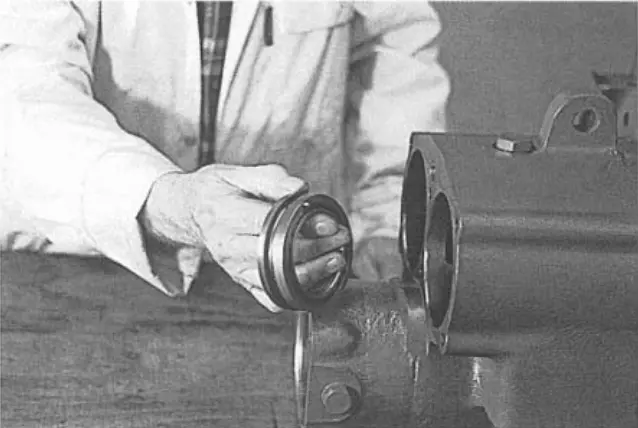 figure 111. Floating “mother” bushing figure 111. Floating “mother” bushing |
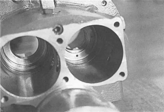 figure 112. Outlet cover hole figure 112. Outlet cover hole |
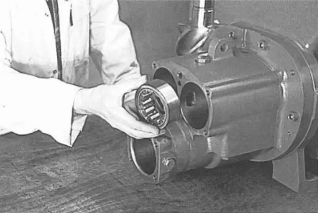 figure 113. “Female” cylindrical roller bearing outer ring and bearings figure 113. “Female” cylindrical roller bearing outer ring and bearings |
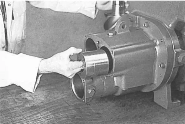 figure 114. Intermediate bearing “mother” figure 114. Intermediate bearing “mother” |
Compressor assembly procedure. Part 2.
Howden compressors
Howden XRV127 Howden XRV163 Howden XRV204 Howden WRV163 Howden WRV204 Howden WrVi255 Howden WrVi321
Technical documentation for XRV 127 compressors
XRV 127 Description XRV 127 operation Dismantling XRV 127 Assembling XRV 127 XRV 127 tools XRV 127 Parts XRV 127 schemes
Technical documentation for XRV 163-204 compressors
xrv 163-204 Description xrv 163-204 operation Dismantling XRV 163-204 XRV 163-204 assembly XRV 163-204 tools XRV 163-204 Spare Parts XRV 163-204 schemes
Technical documentation for WRV compressors - WRVi
WRV description WRV operation WRV 163 repair WRV 204-255-321 repair WRV tools WRV spare parts WRV-WRVI diagrams