- En →
- Zapchasti Kompressorov →
- Kompressory Howden →
- Sborka Xrv163 204 Kompressora
Toros LLC is industrial cold of Europe
Spare parts, repair and maintenance of refrigeration units.
Spare parts for compressors in stock and on order!
call:
WhatsApp
e-mail: storopov86@gmail.com
Complete repair of the XRV 163-204 compressor (assembly instructions)
Part 2. Assembling the compressor
When reassembling, do the following:
1. Reassemble the compressor in a clean area. (Check that the required outer bearing ring has been found for installation in the crankcase).
2. Always refer to the relevant drawing.
3. Always replace consumables when reassembling.
4. Always store replacement parts in their protective packaging until they are needed.
5. Always lubricate components with clean oil before installing them.
6. Always tighten the screws to the required torque value.
7. Always use a flat heat source, such as an oil bath or induction heater, to heat the bearing rings before installation. This will avoid damage and deformation of the bearings.
Assembling the XRV 163-204 compressor
1. Heat the inner ring of the bearing (Figure 35) (Check that the required outer bearing ring has been found for installation in the crankcase).
2. Place the bearing ring on the rotor shaft and fully plug it into place until it “protrudes”. Keep it in place until it cools on the shaft neck. (If this is not done, it will “slide” out of place as it cools down). (Figure 36)
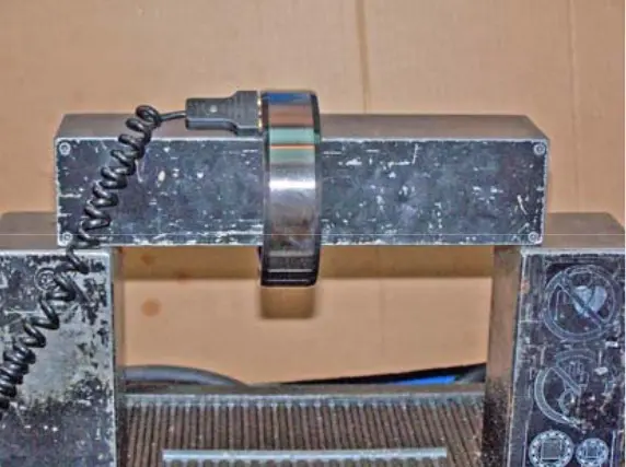 figure 35. Inner bearing ring figure 35. Inner bearing ring |
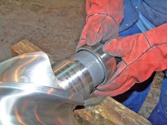 figure 36. Shaft neck seat figure 36. Shaft neck seat |
3. Repeat the above process for the other three inner bearing rings. (Figure 63)
NOTE: Check that the outer and inner rings are not switched between bearings.
4. Lubricate and place the new o-rings on the floating bushing seals and replace the seals in the bearing holes at the outlet end. (Figure 64)
5. Insert the locking pins into the fixing plates of the floating bushing and place them in place in the bearing holes.
6. Check that the locking pins are located in the grooves of the floating bushings. (Figure 37)
7. Lubricate the disc spring washers. Place the spring washer with the convex side inward on the bottom of the crankcase bearing hole at the “dad” outlet. (Figure 38)
8. Install an oil inlet spacer in each opening of the exhaust crankcase bearing; the grooves should point outwards. (Figure 39)
9. Push the outer bearing ring into the “male” bearing hole in the exhaust end housing. (Figure 40) (Check that the right ring is being used).
10. Repeat steps 7, 8, and 9 on the female outlet.
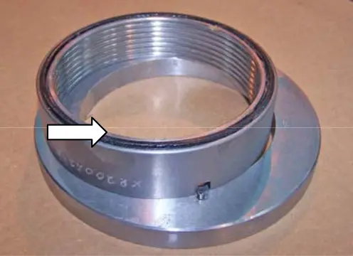 figure 37. Floating bushing groove figure 37. Floating bushing groove |
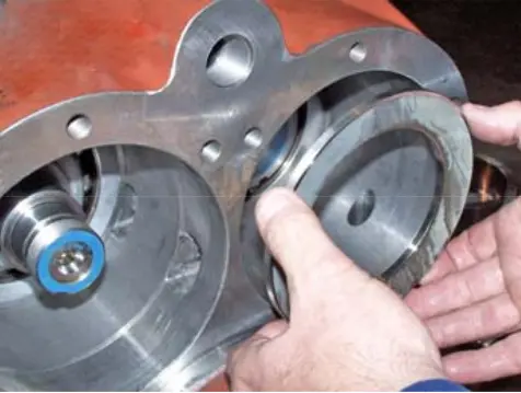 figure 38. Disc spring washer figure 38. Disc spring washer |
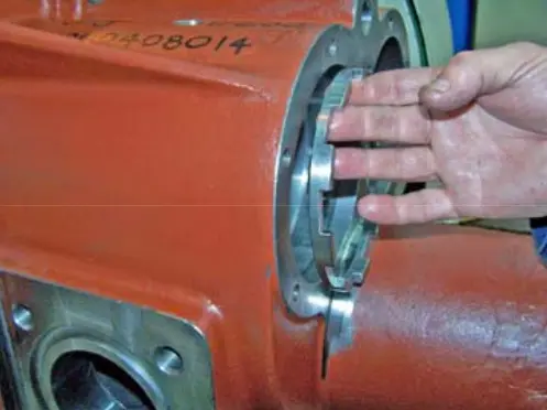 figure 39. Inlet oil spacer figure 39. Inlet oil spacer |
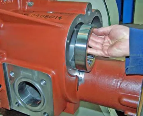 figure 40. Outer bearing ring figure 40. Outer bearing ring |
11. Lubricate the rotors and use the lifting tool to reinstall them into the main crankcase. The easiest way is to install the “mom” rotor first. (Each rotor's center of gravity is approximately at its midpoint).
12. The serial numbers stamped on the rotors must match so that the serial numbers on the outer edge of one “groove” of the rotor “female” coincide with the serial number at the base of one rotor blade “dad” when reinstalled. (Figure 41) Note that some rotor blades do not have serial numbers.
13. Lubricate the spool and place it back in the hole. Insert the spool into the hole as far as you can. (Figure 42)
14. Check that the spool moves freely in its hole.
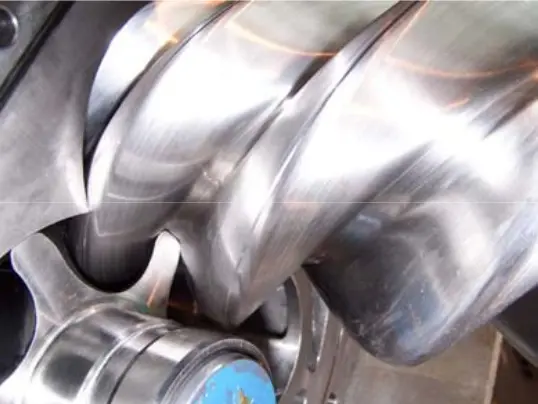 figure 41. Rotors figure 41. Rotors |
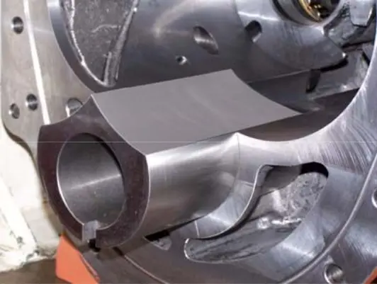 figure 42. Spool figure 42. Spool |
15. Install the new outer bearing rings into the intake case and secure them with locking rings. (Figure 43) Check that the bearings do not hit the O-ring and are fully embedded in their holes.
16. Lubricate and replace the spool return spring. (Figure 44)
17. Lubricate and replace the spool stop. (Figure 45)
18. Replace the inlet end housing (with the new O-ring clutch) using a lifting tool. Secure the crankcase lightly with a few washers and mounting screws. Reinsert the reference pins using a soft mallet. (Check that the screw extraction hole in the pin is open).
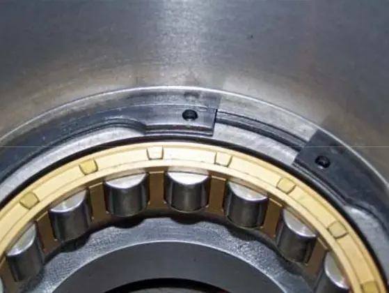 figure 43. Outer bearing ring retaining ring figure 43. Outer bearing ring retaining ring |
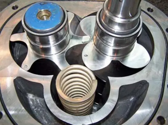 figure 44. Spool return spring figure 44. Spool return spring |
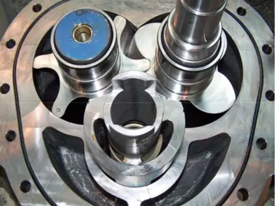 figure 45. Spool stop figure 45. Spool stop |
19. Replace the rest of the washers and mounting screws and tighten them to the recommended value.
20. Heat the inner ring of the thrust bearing cartridge evenly to 20 degrees Celsius above the ambient temperature.
21. Place the unit on the rotor exhaust shafts, ensuring that the cartridge is correctly oriented. (Figure 46)
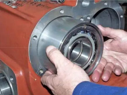 figure 46. Thrust bearing cartridge
22. Place a special tool (disc spring loader) into the hole and tighten to 50 Nm using mounting screws and washers (this compresses the disc washer and ensures the correct torque value that can be applied to the thrust bearing fixing nut) (Figure 47).
23. Install the fixing nut without the lock plate and tighten it to the specified value using a special tool (M50 lock nut (XRV163) and M65 (XRV204) (Figure 48).
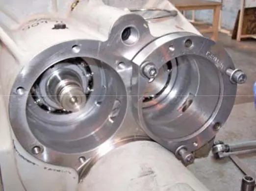 figure 47. Thrust bearing fixing nut figure 47. Thrust bearing fixing nut |
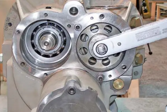 figure 48. Locking nut tightening figure 48. Locking nut tightening |
24. Remove the lock nut, install the spring washer, replace the lock nut and tighten it to its full value. (Figure 49).
25. Repeat this process to assemble another thrust unit.
26. Install the discharge drum and the spacer lock pins on the exhaust end housing. (Figure 50)
27. Insert the discharge drum bushing without o-rings or insert the labyrinth insert into the “dad” hole of the exhaust end, making sure that it is fixed to the lock pin. (Figure 51)
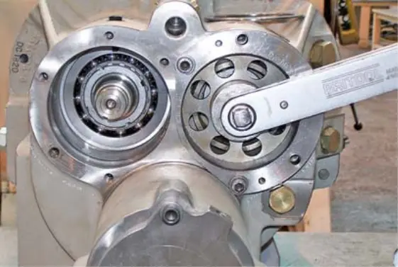 figure 49. Counternut figure 49. Counternut |
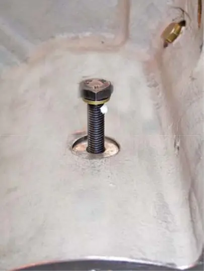 figure 50. Locking pins figure 50. Locking pins |
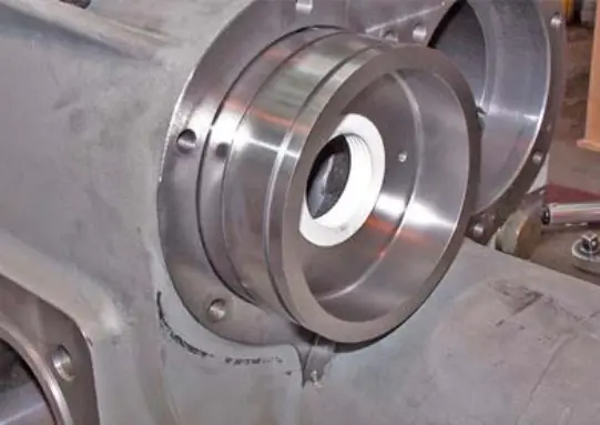 figure 51. Discharge drum bushing figure 51. Discharge drum bushing |
28. Set the “male” rotor exhaust gap as follows:
Install an indicator with a limb to check the exhaust end clearance. Set the sensor to zero, set the cover bar without an o-ring and tighten the cap bar mounting screws and record the sensor reading (Figures 52 and 53).
Remove the cover plate of the discharge drum bushing and sharpen the bushing to set the exhaust end gap.
The volume of material removed from the bushing is equal to the sensor reading minus the required clearance at the exhaust end of the rotor.
Replace the discharge drum bushing and the cover bar, set the sensor to zero and tighten the cover bar mounting screws and check that the sensor reading equals the required rotor outlet clearance.
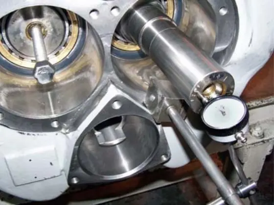 figure 52. Indicator with limb figure 52. Indicator with limb |
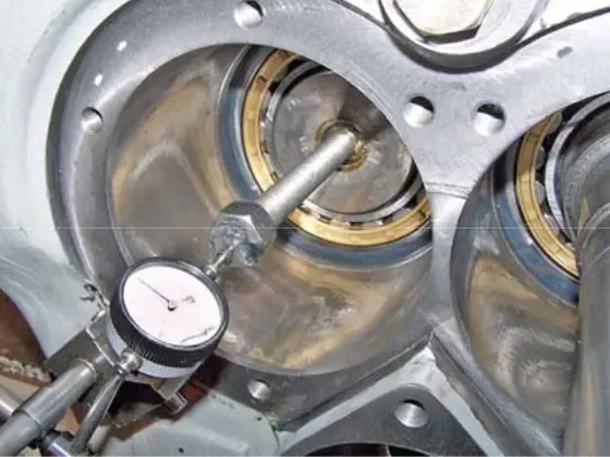 figure 53. Sensor readings figure 53. Sensor readings |
29. Remove the cover bar and the discharge drum bushing.
30. Install the replaceable labyrinth liner seal into the discharge drum bushing as follows:
Place the Loctite 275 on the outer diameter of the labyrinth liner seal and push the seal into the discharge drum bush.
31. Lubricate and install the o-rings on the discharge drum bushing and the rotor cover bar; replace them, making sure that the drum bushing o-rings do not lock as they pass through the oil channel. Replace the tie bolts and fully tighten them.
32. Insert the spacer into the “mother” hole in the exhaust end, making sure that it is fixed to the lock pin. (Figure 55)
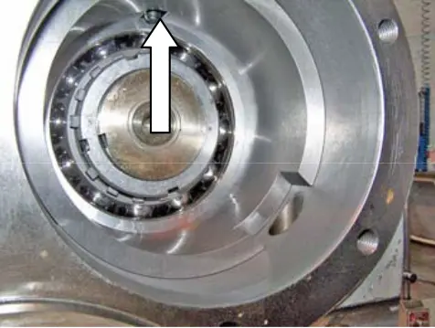 figure 55. Spacer lock pin figure 55. Spacer lock pin |
|
33. Install the cover bar without an o-ring and insert it into place.
34. Repeat the process of setting the gap for the “female” rotor and spacer, adjust the gap by sharpening the spacer to the required value.
35. Remove the cover bar, grease and install the sealing ring, replace the mounting screws, and tighten them completely.
36. Check that the spool moves freely in its hole (Figure 56).
37. Lubricate and replace the spool stop return spring (Figures 57 and 58)
38. Replace the inlet end housing (with the new O-ring clutch) using a lifting tool.
39. Lightly secure the crankcase with several washers and mounting screws and replace the reference pins with a soft mallet. (Check that the screw extraction hole in the pin is open).
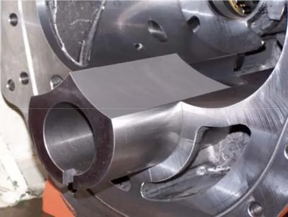 figure 56. Spool figure 56. Spool |
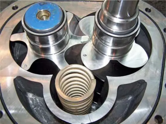 figure 57. Spool return spring figure 57. Spool return spring |
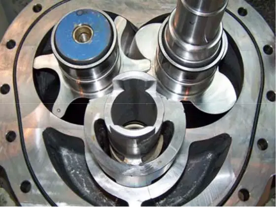 figure 58. Spool stop figure 58. Spool stop |
40. Check that the rotors can rotate in the crankcases.
41. Replace the rest of the washers and mounting screws and tighten them to the recommended value.
42. Check again that the rotors can rotate in the crankcases.
43. Replace the discharge drum bushing, making sure that the bushing is on the lock pin. (Figure 59)
44. Replace the cover bar and check that the clearance at the exhaust end of the rotor is within the error range. Install the indicator with a limb at the inlet end of the rotor “dad”. (Figure 60) Set the indicator to zero and loosen the mounting screws that secure the shaft cover at the rotor outlet end. The indicator reading obtained reflects the gap at the exhaust end of the rotor. Check the gap within the margin of error.
45. Repeat the same steps with the “female” rotor using the specified extension screw. (Figure 61)
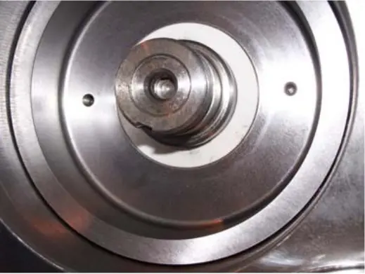 figure 59. Discharge drum bushing figure 59. Discharge drum bushing |
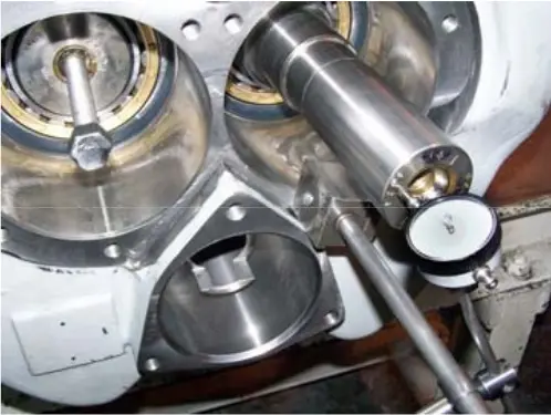 figure 60. Indicator with limb figure 60. Indicator with limb |
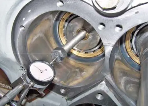 figure 61. Extension screw figure 61. Extension screw |
46. Lubricate and install the o-rings on the discharge drum bushing, replace the bushing, making sure that the o-rings are not damaged by the oil channel between the two holes. (Figure 62)
47. Repeat the procedure from step 9 for the spacer on the “mother” side of the rotor.
48. Lubricate and replace the discharge drum on the female exhaust shaft (Figure 63) and secure it with a new spring washer and lock nut. (Figure 64)
49. Using a lock nut wrench, tighten it (Pic. 65) to the recommended value following the procedure.
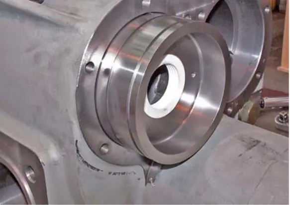 figure 62. Discharge drum bushing sealing rings figure 62. Discharge drum bushing sealing rings |
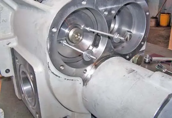 figure 63. Discharge drum figure 63. Discharge drum |
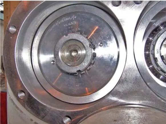 figure 64. Spring washer and lock nut figure 64. Spring washer and lock nut |
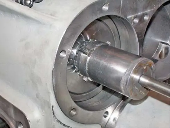 figure 65. Counter-nut wrench figure 65. Counter-nut wrench |
50. Replace and lubricate the o-rings on the cover of the Vi adjustment unit.
51. Lubricate and replace the unit in the intake housing, making sure that the lead protrusions of the Vi adjustment unit are fixed in the spool stop. (Figure 66)
52. Replace the mounting screws and washers and tighten them to the recommended value.
53. Lubricate and install the new o-rings on the exhaust shaft covers and replace them. Check that the marks made during disassembly match when reassembled.
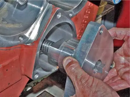 figure 66. Vi Control Unit
54. Replace the washers and mounting screws and tighten them evenly to the recommended value.
55. Lubricate and place the new cuff on the drive drum, ensuring that the cuff is correctly installed in a circular manner (Figure 67). Place the drum seal on the drum and press firmly on the outer edge of the entire sealing circumference until you hear a “click” to indicate that the seal is in place. Failure to do this will result in a preliminary breakdown of the drum seal and the compressor not working properly. Reinstall the O-ring onto the drum using a small amount of grease to secure it (Figure 68).
56. Replace the drive drum seal in the drive cylinder using the extraction rods without damaging the cuff. (Figure 69)
57. Use Loctite 243 to tighten the lock nut and the spool liner thread. Install the spring washer and lock nut on the shaft. Use a special tool to center the drum in the cylinder hole and install the support bracket by securing the mounting screws. Insert the locknut socket into the support bracket and tighten the lock nut to 80 Nm for the XRV163 compressor or 160 Nm for the XRV204 compressor. Check whether the groove in the lock nut is aligned with the M5 screw hole in the drum. Use Loctite 243 to tighten a screw in the drum without a head. Tighten to 10 Nm.
NOTE: Compressors that do not require the installation of a spring washer on the drive drum:
XRV163-MK2C and subsequent models
XRV204-MK3D and subsequent models.
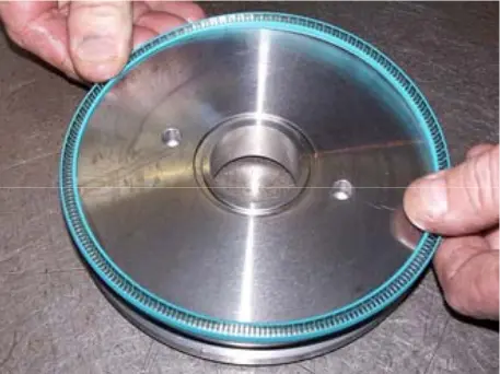 figure 67. Drive drum cuff figure 67. Drive drum cuff |
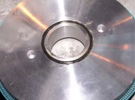 figure 68. Drum sealing ring figure 68. Drum sealing ring |
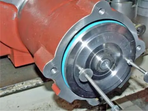 figure 69. Drive drum seal figure 69. Drive drum seal |
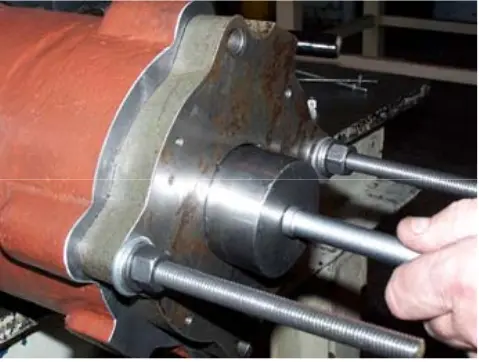 figure 70. Indicator spindle pin figure 70. Indicator spindle pin |
58. Install the indicator spindle guide pin, if it is installed in its own recess, using a small amount of grease to secure it.
59. Lubricate and place the new O-ring on the drive cylinder cover/indicator spindle.
60. Insert the indicator spindle into the piston rod hole, making sure that the guide pin enters the recess marked during disassembly. On compressors equipped with a linear position sensor, securely insert the sensor into an aluminum tube attached to the spool rod.
61. Install the minimum cylinder power stops and use the threaded rod used to disassemble the drive cylinder cover and install the washers and mounting screws to put it back in place (Figures 71 and 72). Tighten them to the recommended value.
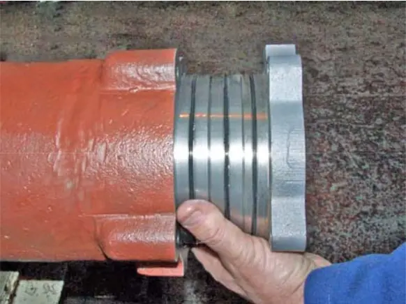 figure 71. Drive cylinder cover figure 71. Drive cylinder cover |
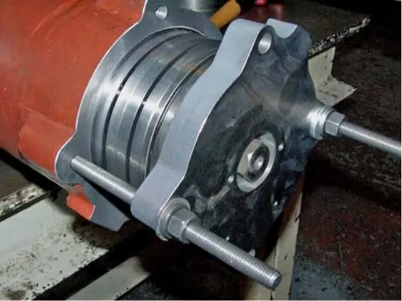 figure 72. Installing the cover figure 72. Installing the cover |
62. Lubricate and install the new O-ring on the inlet end “female” shaft cover and replace the shaft cover. (Figure 73)
63. Replace the washers and mounting screws and tighten them evenly to the recommended value.
64. Lubricate and replace the labyrinth seal on the drive shaft, making sure that the drive pin is locked in the groove. (Figure 74)
65. Install a new shaft seal, making sure that the seal is fixed to the drive pin in the labyrinth seal. (Figure 75)
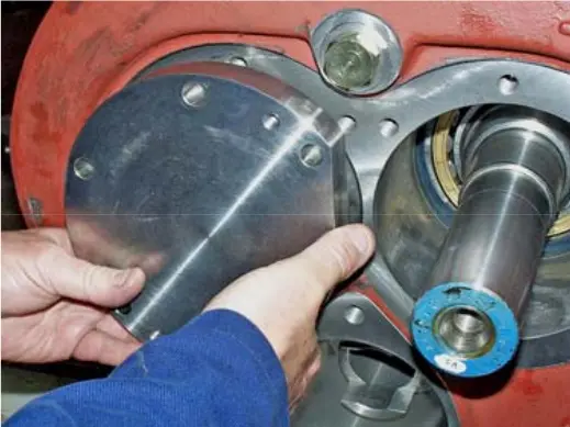 figure 73. “Mom” shaft cover figure 73. “Mom” shaft cover |
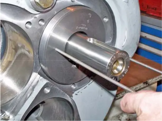 figure 74. Labyrinth seal figure 74. Labyrinth seal |
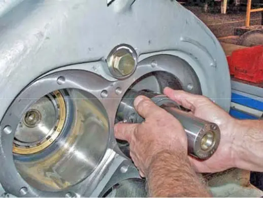 figure 75. Shaft seal figure 75. Shaft seal |
66. Install the new O-rings and the fixed shaft seal seat on the inlet end drive shaft cover (Figure 76) and replace the drive shaft cover. (Figure 77)
67. Replace the washers and mounting screws and tighten them evenly to the recommended value. Performing this operation inaccurately may damage the shaft seal (Figure 78).
68. Replace the oil drain plug on the bottom of the intake crankcase (Figure 79).
69. If the compressor has been removed from its base for inspection, replace it and re-align it.
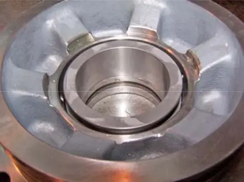 figure 76. Shaft seal seat figure 76. Shaft seal seat |
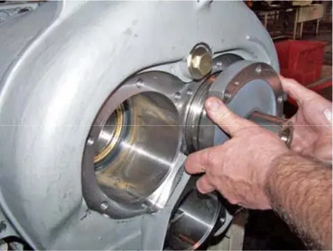 figure 77. Drive shaft cover figure 77. Drive shaft cover |
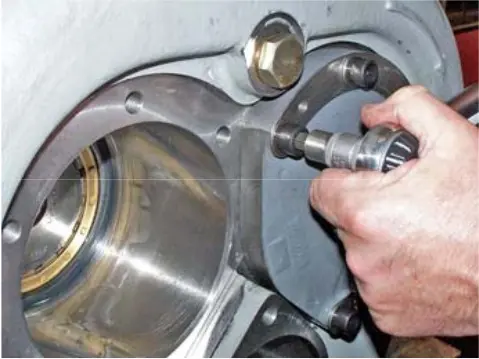 figure 78. Mounting screws figure 78. Mounting screws |
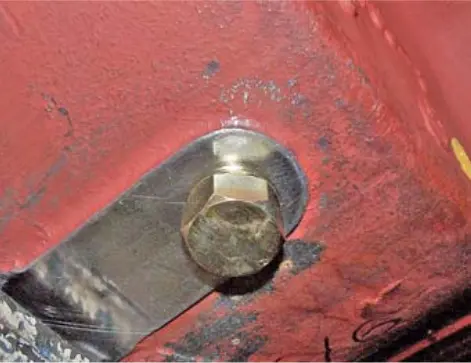 figure 79. Oil drain plug figure 79. Oil drain plug |
70. Replace and reconnect electrical equipment that was removed when disassembling the drive cylinder. (Figure 80)
71. Replace the microswitch cover and secure it with mounting screws. (Figure 81)
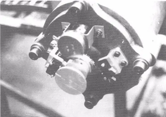 figure 80. Microswitch figure 80. Microswitch |
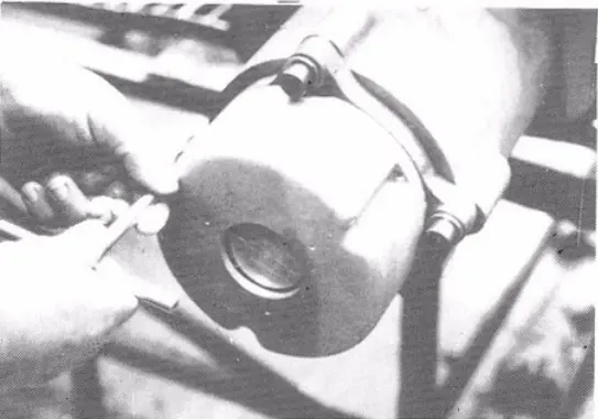 figure 81. Microswitch cover figure 81. Microswitch cover |
NOTE: Place the Vi adjusting screw back in its original position.
Howden compressors
Howden XRV127 Howden XRV163 Howden XRV204 Howden WRV163 Howden WRV204 Howden WrVi255 Howden WrVi321
Technical documentation for XRV 127 compressors
XRV 127 Description XRV 127 operation Dismantling XRV 127 Assembling XRV 127 XRV 127 tools XRV 127 Parts XRV 127 schemes
Technical documentation for XRV 163-204 compressors
xrv 163-204 Description xrv 163-204 operation Dismantling XRV 163-204 XRV 163-204 assembly XRV 163-204 tools XRV 163-204 Spare Parts XRV 163-204 schemes
Technical documentation for WRV compressors - WRVi
WRV description WRV operation WRV 163 repair WRV 204-255-321 repair WRV tools WRV spare parts WRV-WRVI diagrams