- En →
- Zapchasti Kompressorov →
- Kompressory Howden →
- Razborka Xrv127 Kompressora
Toros LLC is industrial cold of Europe
Spare parts, repair and maintenance of refrigeration units.
Spare parts for compressors in stock and on order!
call:
WhatsApp
e-mail: storopov86@gmail.com
Dismantling the XRV127 compressor during overhaul
Compressor disassembly procedure
Safety precautions should be taken before disassembling the compressor.
1. Isolate the drive element.
2. Lower the pressure and purge the system.
3. Disconnect the drive element clutch from the compressor.
4. Place the vessel under the outlet end of the compressor to capture oil.
which may spill out of the hydraulic cylinder when the cylinder cover is removed or the crankcases are separated.
5. Check the reliability and performance of all lifting equipment, i.e. eye bolts, belts and clamps.
Remember that the compressor spool is under spring load and therefore, to avoid injury, the operator should check that the spring is not tensioned before disassembling. This can be done by checking that the spool is completely unloaded (the piston must be at its maximum distance towards the outlet) and that the liquid coefficient adjustment is at its minimum value (the Vi adjusting screw should be turned clockwise to its limit value).
Disconnect/remove any installed electrical equipment if it prevents further disassembly.
1. Place the vessel under the crankcase at the inlet end, remove the hexagonal plug from the bottom of the crankcase at the inlet end, and drain off the oil. (Figure 10)
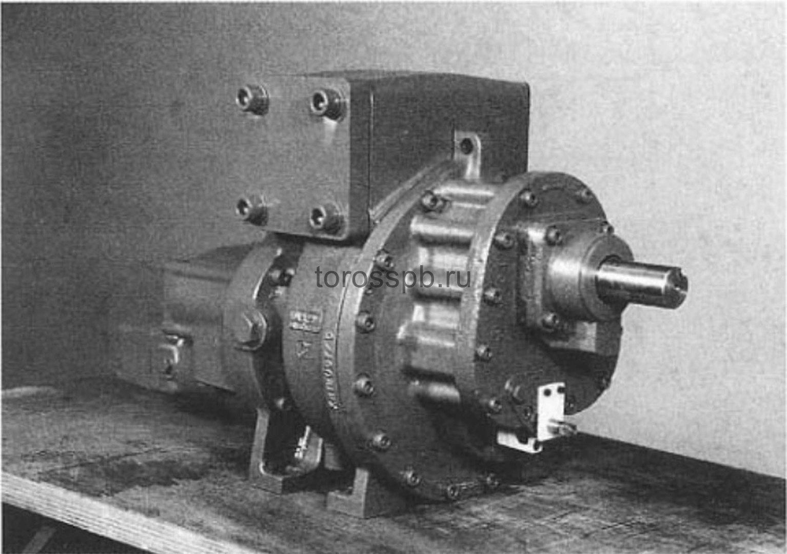 Fig.11 Dismantling the xrv127 compressor Fig.11 Dismantling the xrv127 compressor |
|
Removing the Vi indicator node
1. Loosen and remove the 2 mounting screws that secure the base plate and pull this plate out. (Figure 12)
2. You can then remove the bushing mounting ring by loosening the two splined installation screws and pulling it out of the barrel with a sliding stop. (Figure 13)
3. You can then remove the indicator and screw bushing. Remove the index post by removing the slotted mounting screw.
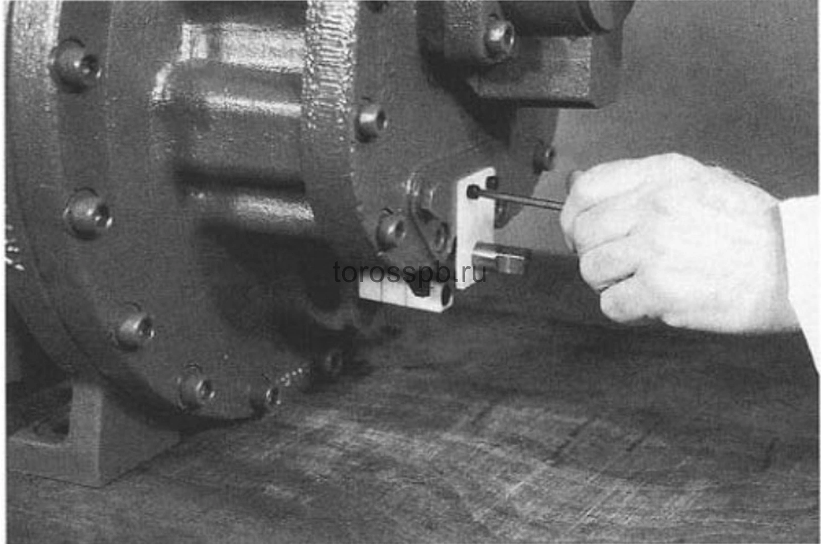 fig. 12. Base plate fig. 12. Base plate |
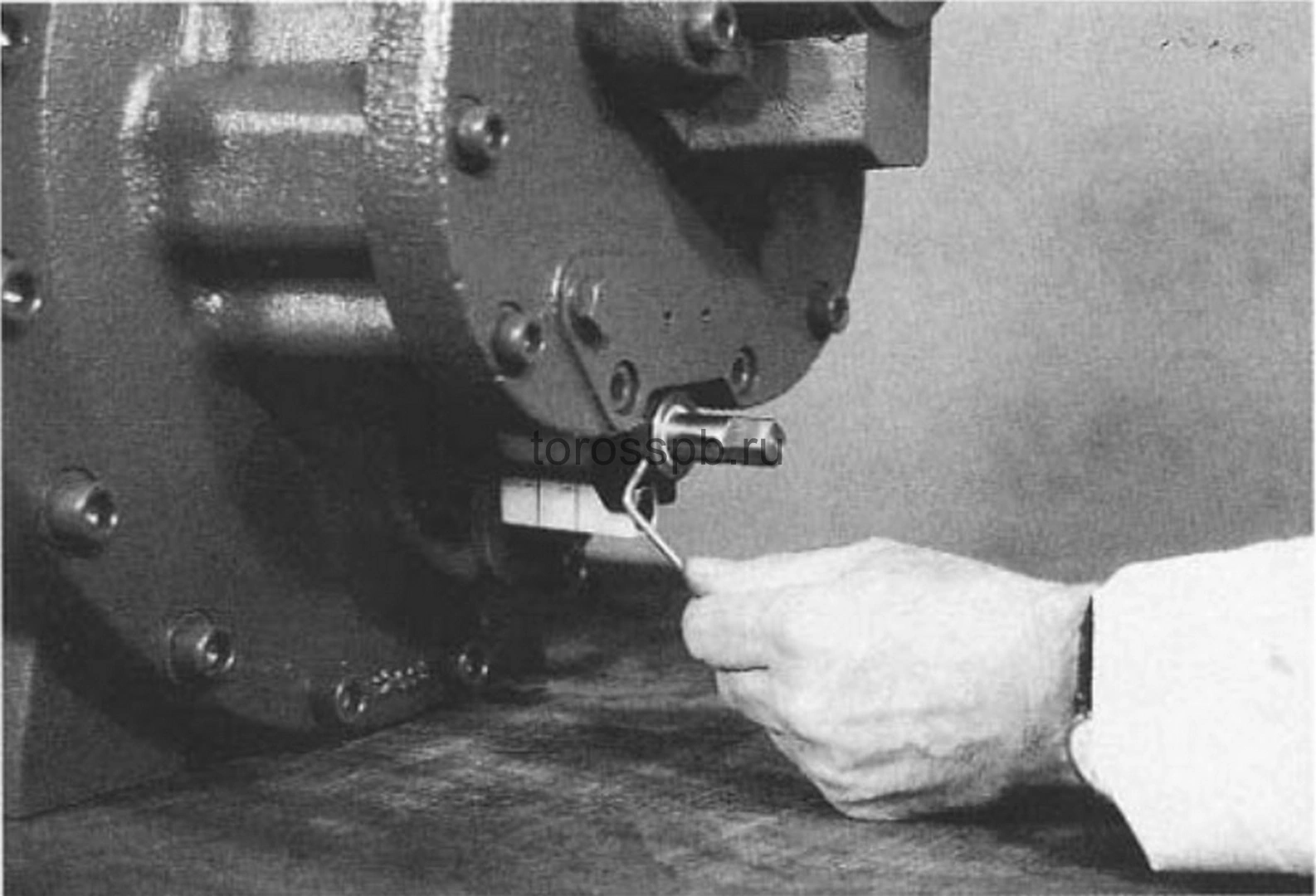 figure 13. Sleeve mounting ring figure 13. Sleeve mounting ring |
Removing the intake shaft seal
4. Remove the intake shaft seal sleeve from the inlet (drive) shaft. Remove the 4 mounting screws (Figure 14) and remove the seal body. (Figure 15). Assemble the sealing ring of the seal body, the fixed seat must remain in the seal body.
5. Loosen the 3 screws without the head that secure the shaft seal to it. (Figure 16)
6. Carefully remove the shaft seal from the intake shaft. (Figure 17) Remove the fixed drive shaft seat and sealing ring from the seal body.
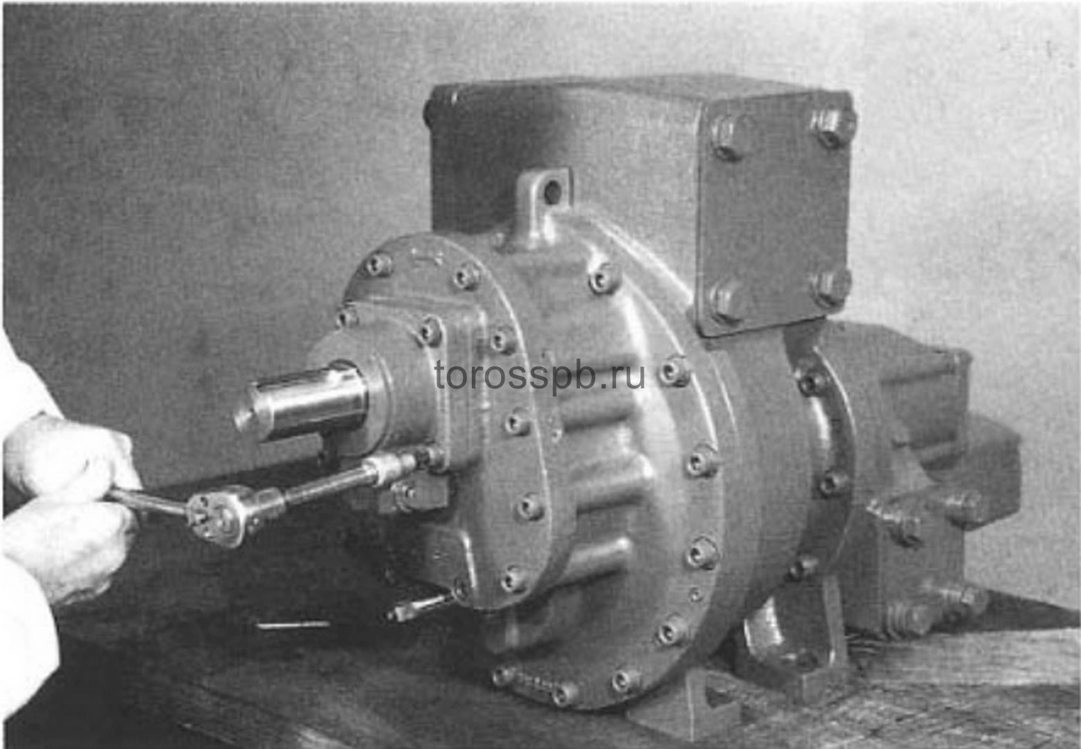 figure 14. Seal body mounting screws figure 14. Seal body mounting screws |
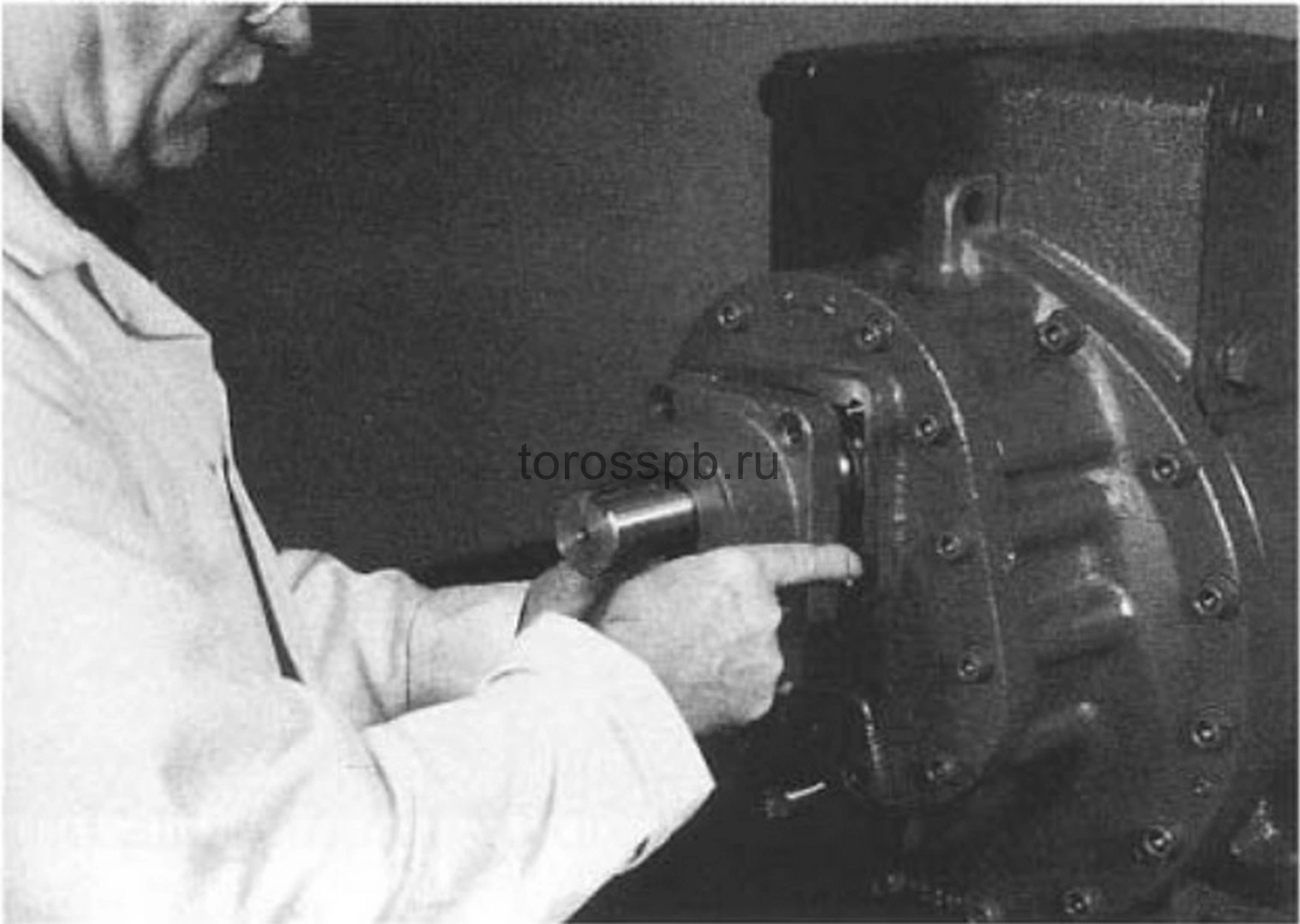 fig. 15. Sealing body fig. 15. Sealing body |
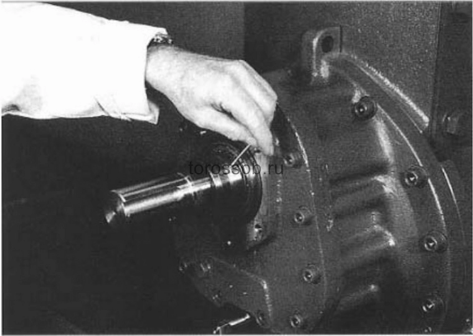 fig. 16. Shaft seal fastening screws fig. 16. Shaft seal fastening screws |
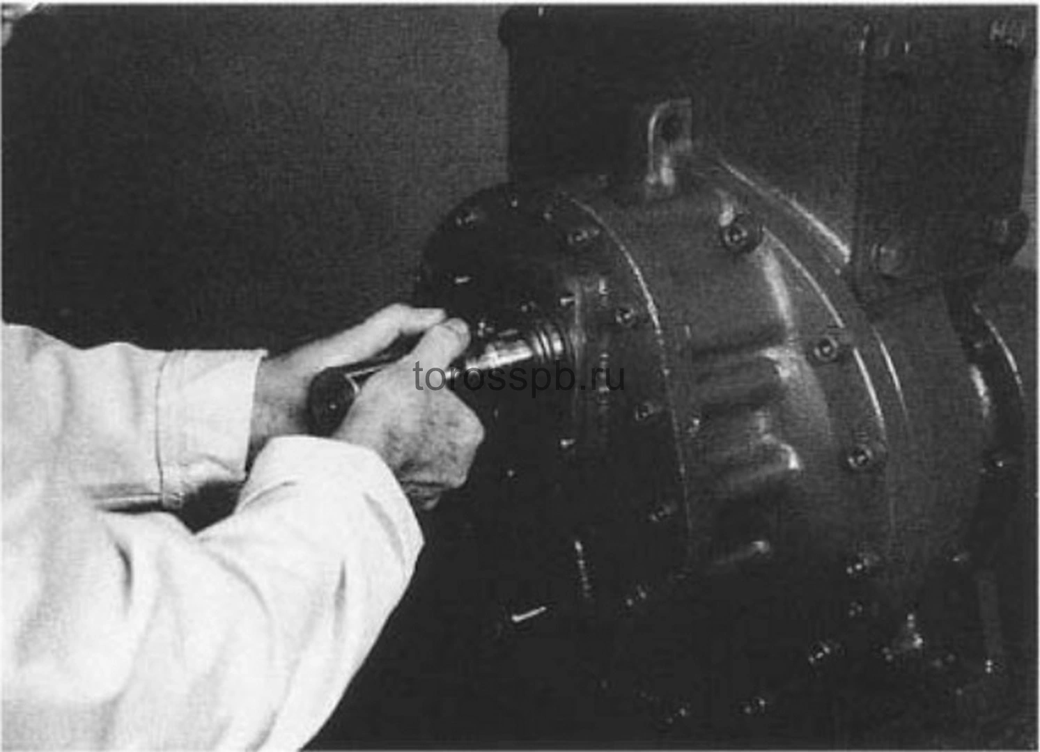 figure 17. Remove the shaft seal figure 17. Remove the shaft seal |
Reducer cover
7. Loosen the slotted mounting screws of the gearbox cover. (Figure 18)
8. Insert the M10 guide rod. (Figure 19)
9. Remove the gearbox cover that supports both the drive shaft and the gear. (Figure 20)
10. Assemble the sealing ring. (Figure 21)
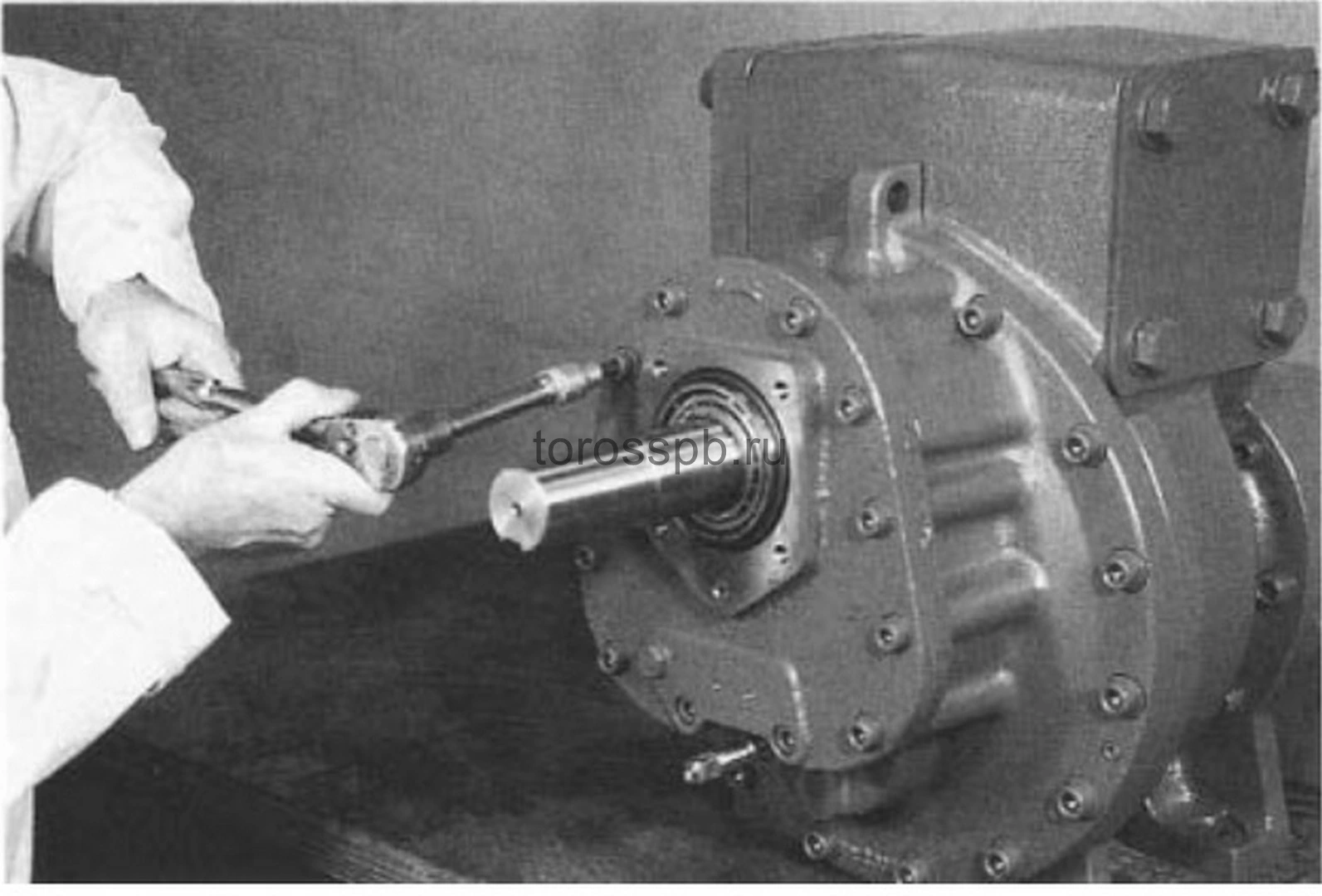 figure 18. Slotted gearbox cover screws figure 18. Slotted gearbox cover screws |
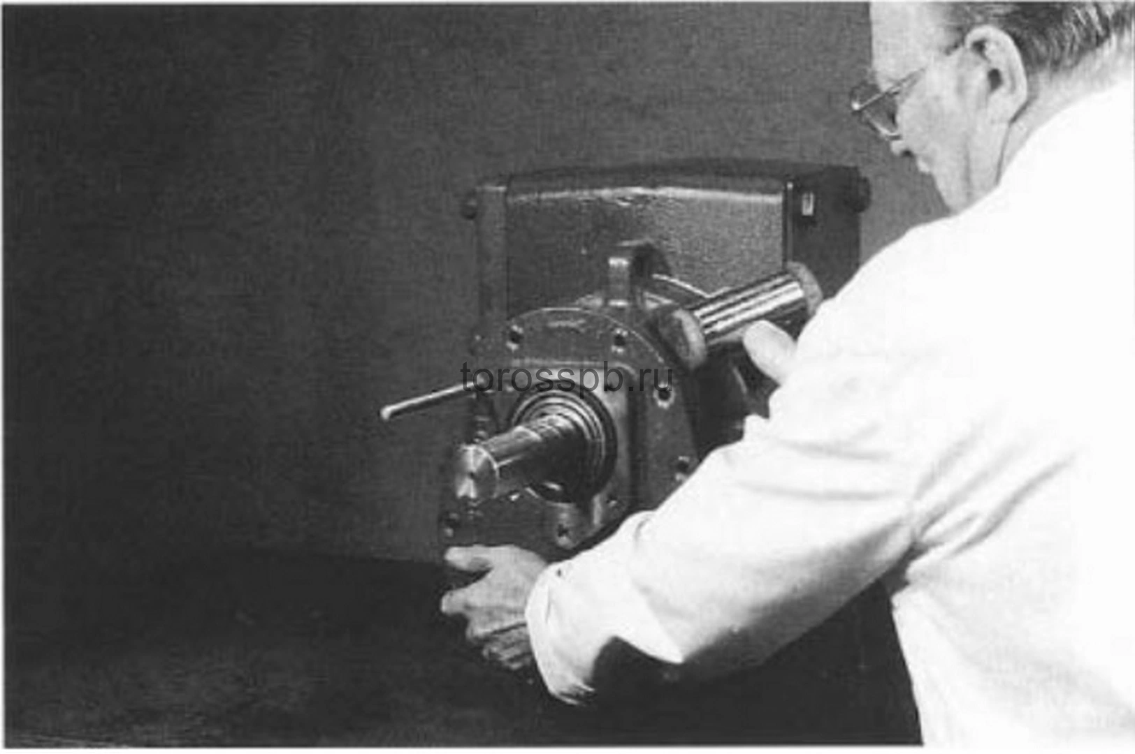 figure 19. M10 guide rod figure 19. M10 guide rod |
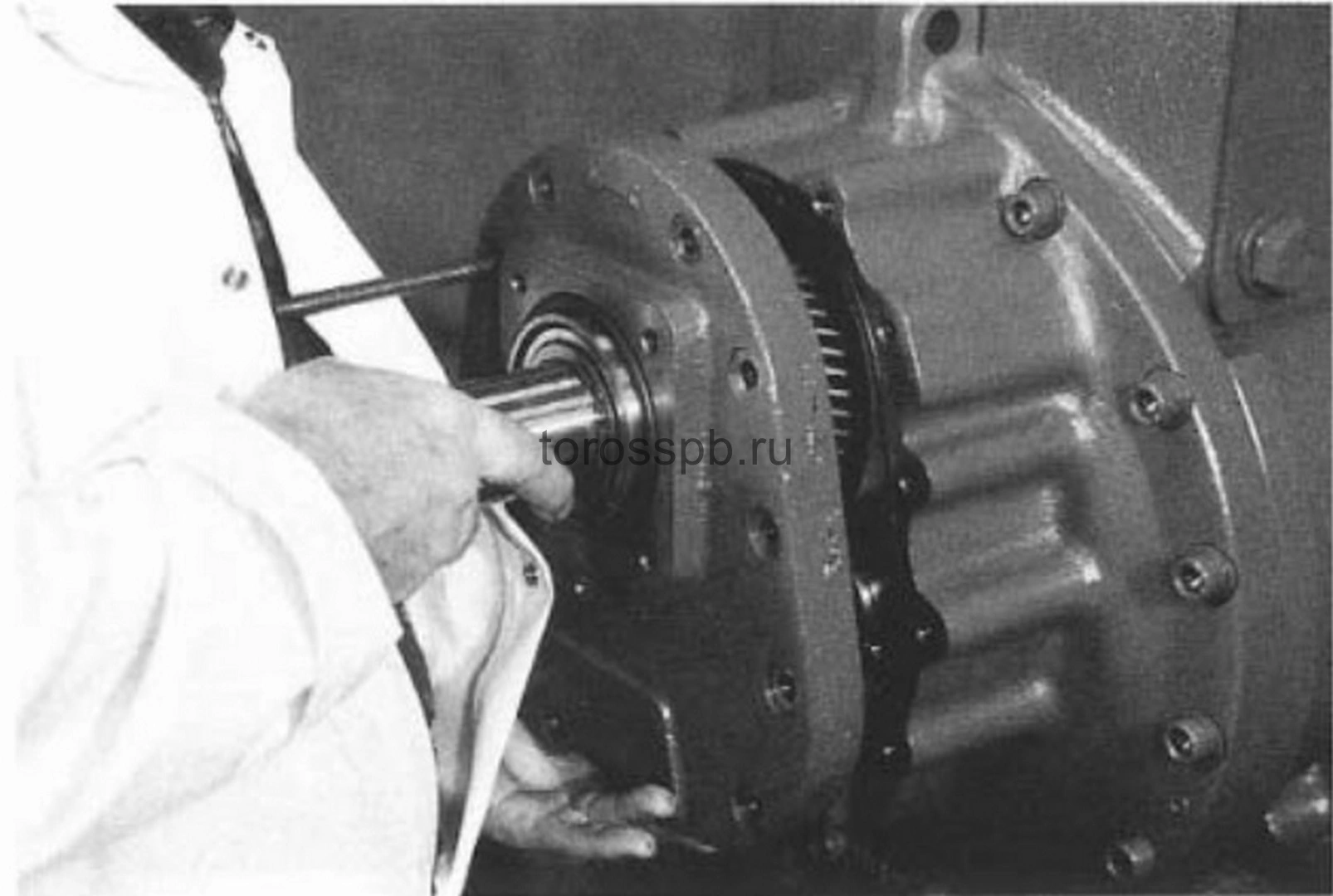 figure 20. Reducer cover figure 20. Reducer cover |
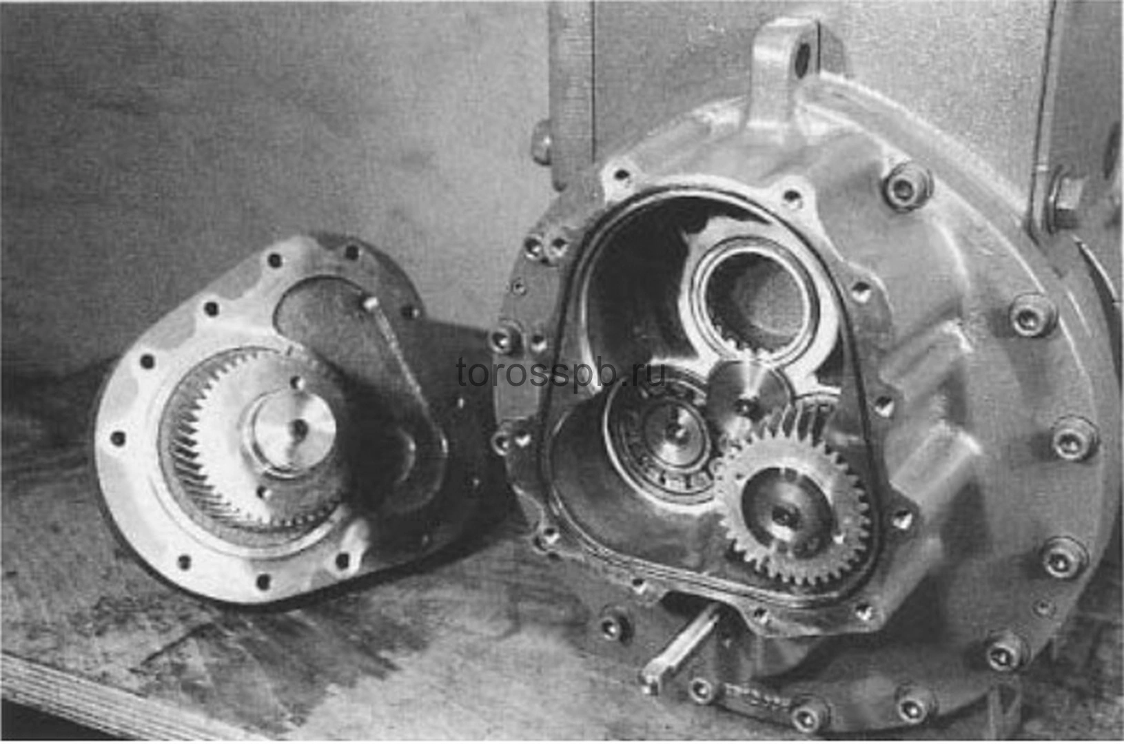 figure 21. Gearbox cover sealing ring figure 21. Gearbox cover sealing ring |
Removing the drive gear and its bushing
11. Remove the drive gear screw and the washer at the end of the rotor “dad”. (Figure 22)
12. Remove the drive gear from the “male” rotor using the XR12008J extraction tool. (Figure 23)
13. Remove the drive gear bush. (Figure 24)
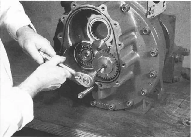 figure 22. Drive gear screw figure 22. Drive gear screw |
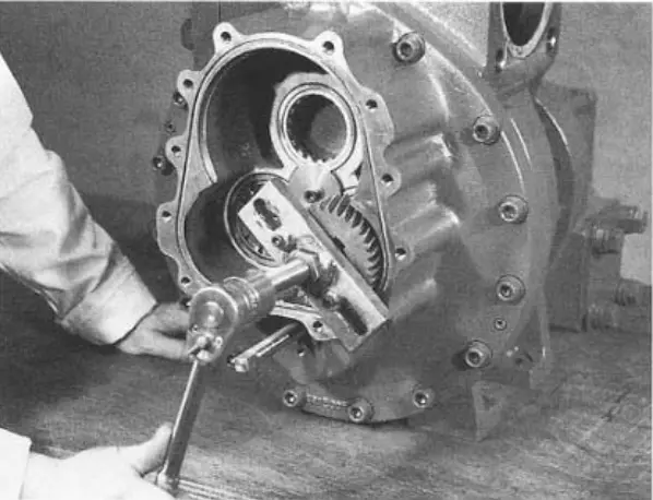 figure 23. Rotor drive gear “dad” figure 23. Rotor drive gear “dad” |
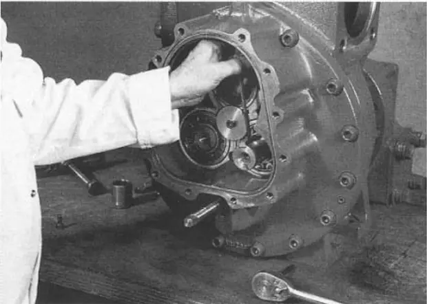 figure 24. Drive gear bush figure 24. Drive gear bush |
Removing the power control limit switch unit
14. Remove the two upper mounting screws (Figure 25) that secure the limit switch cover and remove the cover. (Figure 26) This will allow access to microswitches and potentiometers.
15. Remove the four slotted mounting screws that secure the cylinder end cover (Figure 27) and remove the drive spindle/limit switch. (Figure 28)
Some compressors have an LPI sensor, which is installed as an option instead of switches, and do not have a cylinder switch cover.
NOTE: The indicator spindle must release the mounting pin that moves along the screw slot in the spindle, so this unit must be in an axial position during shooting until the spindle releases the dowel. The LPI sensor is securely located inside the sensor; this unit must also be photographed axially. Be careful when removing the cover to avoid damaging the LPI sensor casing attached to the cover.
IMPORTANT - so that the screw slot that secures the mounting pin is marked for proper reassembly to avoid damage to the potentiometer.
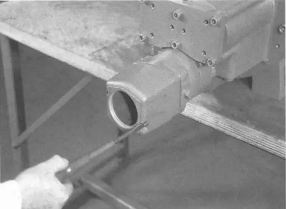 figure 25. Limit switch cover mounting screws figure 25. Limit switch cover mounting screws |
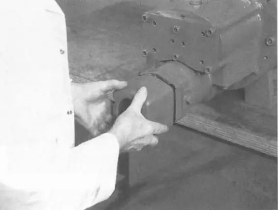 figure 26. Limit switch cover figure 26. Limit switch cover |
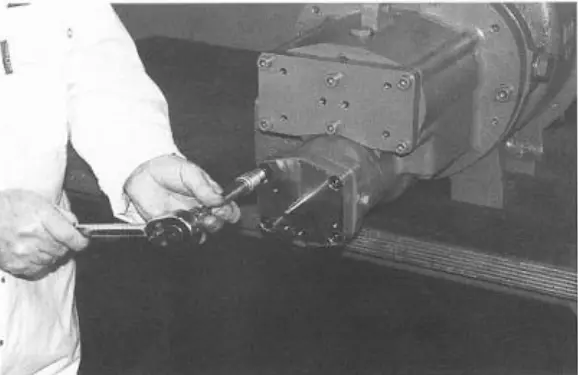 figure 27. Slotted cylinder end cap screws figure 27. Slotted cylinder end cap screws |
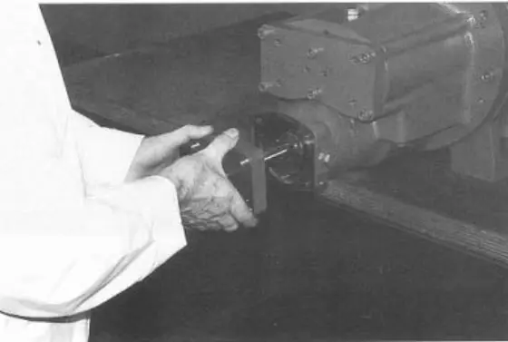 figure 28. Drive spindle/limit switch figure 28. Drive spindle/limit switch |
Removing the drive drum
16. When the drive drum is fully unloaded, bend the tab on the spring washer back. Some XRV127 compressors do not have a lock plate. (Figure 29)
17. Loosen and remove the lock nut (Figure 30) and spring washers. (Figure 31)
18. The drive drum can then be removed using extraction tools. (Figure 32)
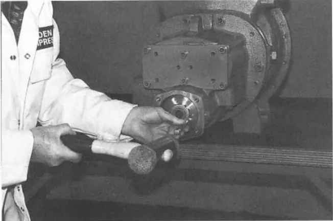 figure 29. Drive drum spring washer tab figure 29. Drive drum spring washer tab |
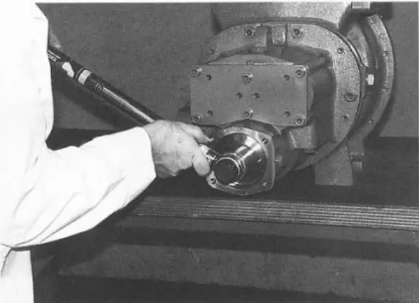 figure 30. Drive drum lock nut figure 30. Drive drum lock nut |
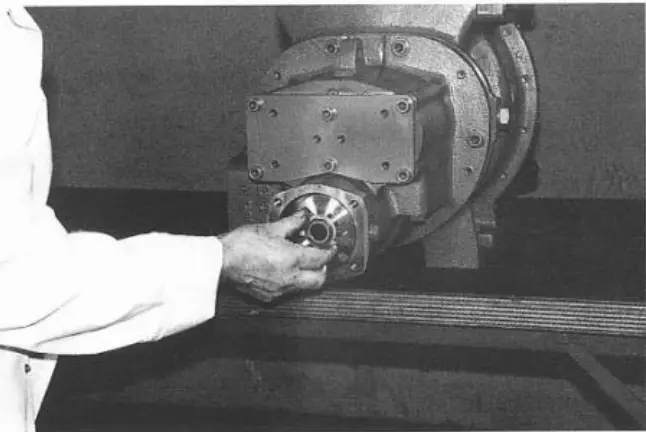 figure 31. Drive drum spring washers figure 31. Drive drum spring washers |
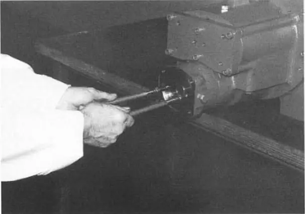 figure 32. Drive drum figure 32. Drive drum |
Removing the rotor end cover plate
19. Remove the 6 slotted installation screws. (Figure 33)
20. Loosen and remove the 6 slotted mounting screws that secure the rotor end cover plate. (Figures 34 and 35)
21. Remove the rotor end cover plate to gain access to the “dad” and “mom” rotors. (Figure 36)
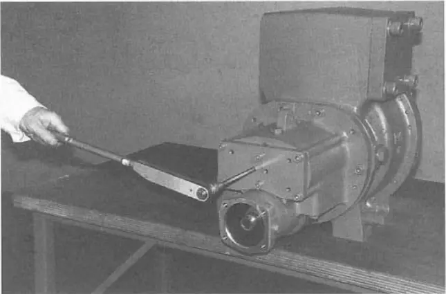 figure 33. Rotor end cover plate installation screws figure 33. Rotor end cover plate installation screws |
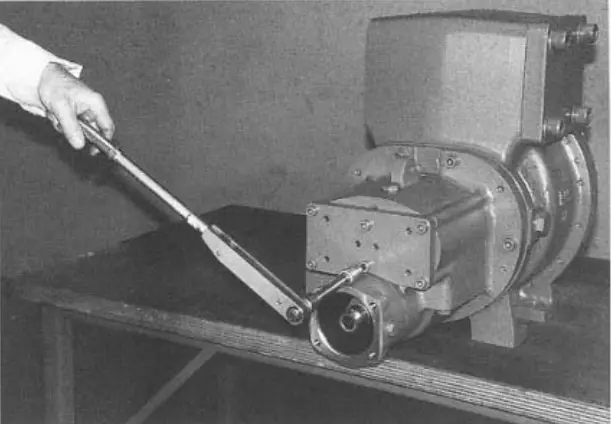 figure 34. Rotor end cap plate mounting screws figure 34. Rotor end cap plate mounting screws |
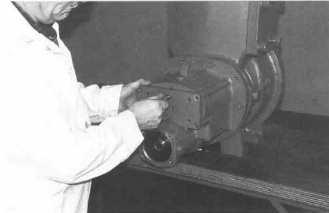 figure 35. Remove the rotor end cover plate mounting screws figure 35. Remove the rotor end cover plate mounting screws |
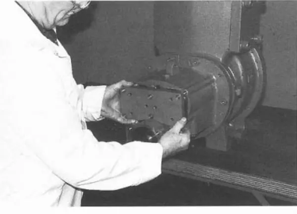 figure 36. Rotor end cover plate figure 36. Rotor end cover plate |
Removing the rotor thrust cover
22. Locate and remove the “dad” and “mother” rotor stop covers using a suitable threaded rod as an extraction tool. (Figure 37)
23. Now there is access to the disc springs of the “dad” and “mom” rotors. (Figure 38)
24. Locate and assemble disc springs. (Figure 39)
Removing the “mom” spacer
25. Remove the “mom” spacer. (Figure 40)
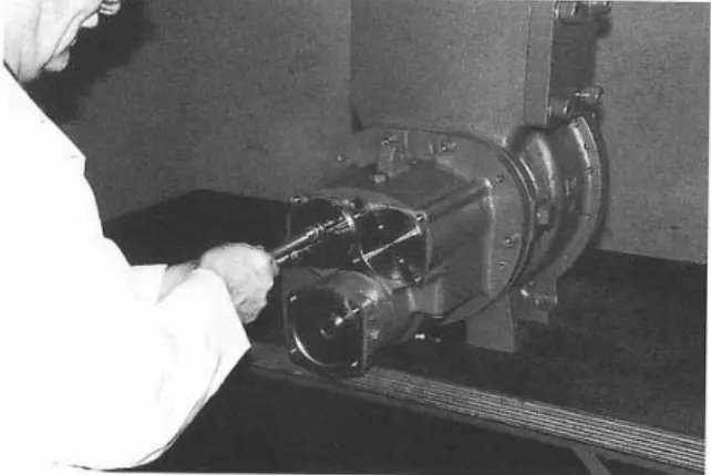 figure 37. Rotor thrust covers figure 37. Rotor thrust covers |
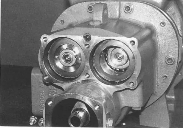 figure 38. Rotor disc springs figure 38. Rotor disc springs |
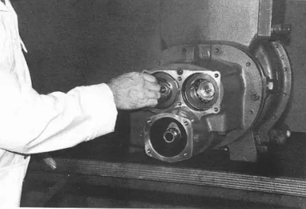 figure 39. Assemble disc springs figure 39. Assemble disc springs |
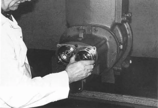 figure 40. “Mom” spacer figure 40. “Mom” spacer |
Removing the discharge drum
There are 2 ways to fix the rotors if you want to tighten or loosen them
lock nuts:
1. Insert the nylon key between the rotors (through the channel at the inlet end).
2. Use a special XR12012J wrench mounted on the intake
rotor shaft “dad”. (Figure 43)
26. While the rotors are locked, release the spring washer (Figure 41) and remove the lock nut from the rotor “dad” using the XR12005J tool. (Figure 42)
27. Remove the discharge drum using a suitable M6 threaded rod as an extraction tool and remove the o-rings. (Figure 44)
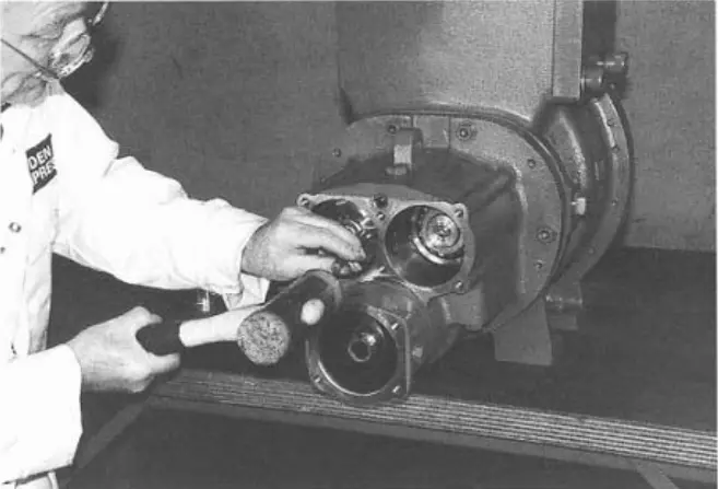 figure 41. Rotor spring washer “dad” figure 41. Rotor spring washer “dad” |
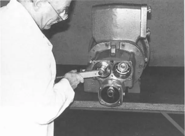 figure 42. Rotor lock nut “dad” figure 42. Rotor lock nut “dad” |
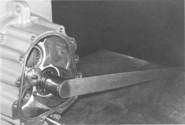 figure 43. XR12012J Wrench figure 43. XR12012J Wrench |
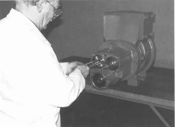 figure 44. O-rings figure 44. O-rings |
28. Remove the discharge drum bushing together with the labyrinth insert using the XR12008J jack support. (Figures 45 and 46)
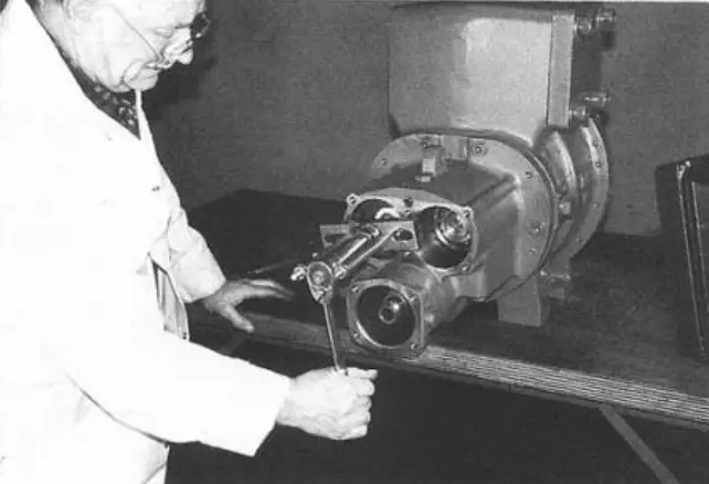 figure 45. Discharge drum bushing with labyrinth insert figure 45. Discharge drum bushing with labyrinth insert |
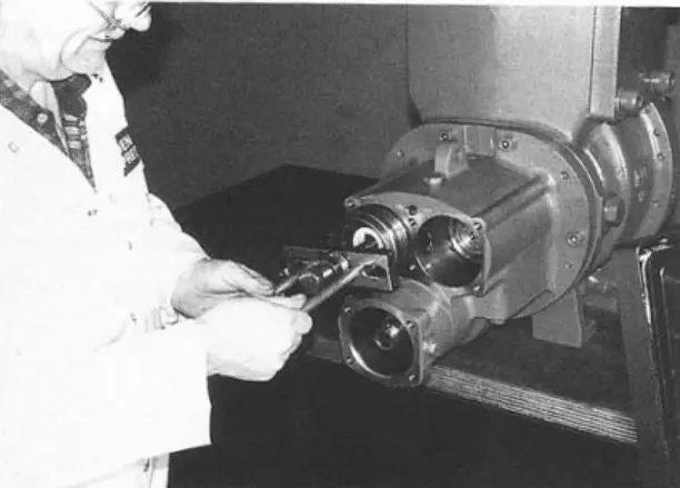 figure 46. XR12008J Jack Support figure 46. XR12008J Jack Support |
29. Disconnect both spring washers: “dad” and “mom”. (Figure 47) For these lock nuts, a special XR12006J wrench, shown in Figure 48, is made.
30. Remove the “dad” lock nut (Figure 49), remembering to stop the rotors from rotating in an appropriate way. (Figure 50)
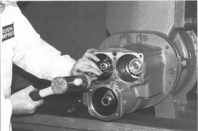 figure 47. “dad” and “mom” spring washers figure 47. “dad” and “mom” spring washers |
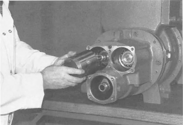 figure 48. XR12006J Special Wrench figure 48. XR12006J Special Wrench |
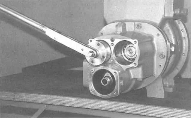 figure 49. Remove the “dad” lock nut with a special key figure 49. Remove the “dad” lock nut with a special key |
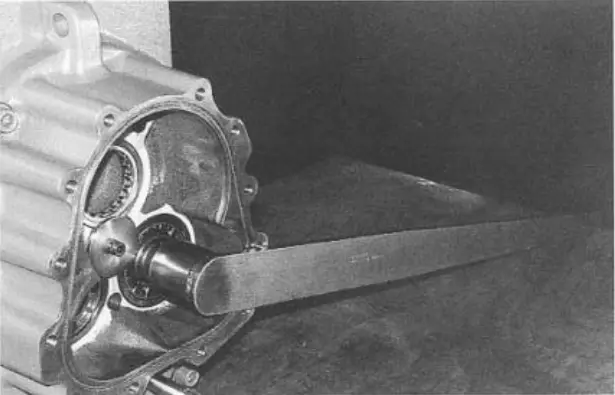 figure 50. Stop the rotors from rotating figure 50. Stop the rotors from rotating |
31. Remove the “mother” lock nut (Figure 51), then remove the “dad” and “mom” spring washers. It is now possible to remove the rotors from the compressor inlet end after removing the gearbox unit.
Removing the gearbox
32. Remove the two internal slotted mounting screws. (Figure 53)
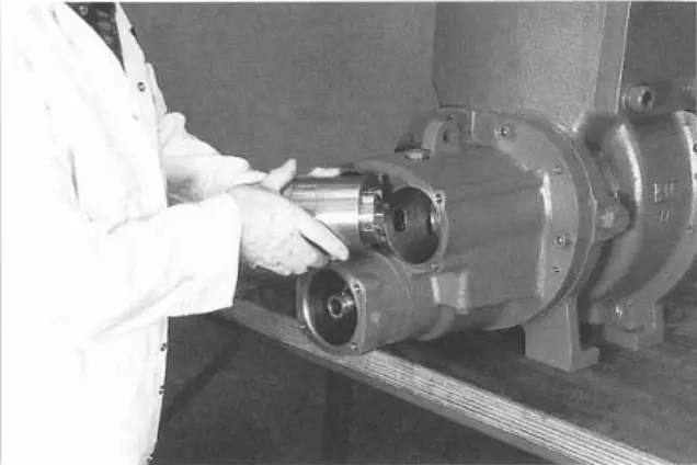 figure 51. “Mom” counternut figure 51. “Mom” counternut |
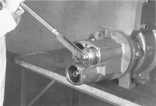 figure 52. Remove the spring washers figure 52. Remove the spring washers |
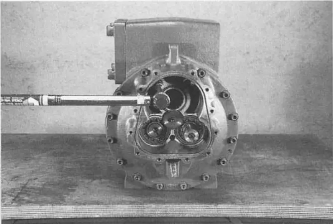 figure 53. Slotted mounting screws figure 53. Slotted mounting screws |
33. Loosen and remove only twelve external slotted mounting screws from the inlet end, leaving one adjacent to each of the two mounting pins. (Figure 54)
34. Using the XR12010J extraction tool (Figure 55), remove the mounting pins from the main crankcase, but do not remove them from the gearbox.
35. Screw two long M12 x 200 guide bars into the selected holes and secure with two nuts. (Figure 56)
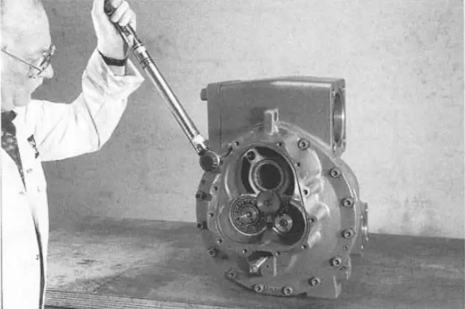 figure 54. External gearbox mounting screws figure 54. External gearbox mounting screws |
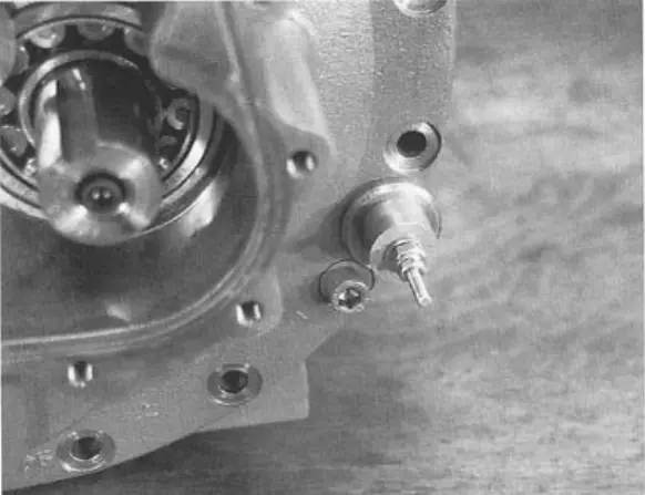 figure 55. XR12010J Extraction Tool figure 55. XR12010J Extraction Tool |
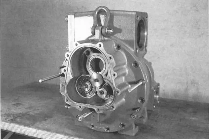 figure 56. M12 x 200 guide rods figure 56. M12 x 200 guide rods |
36. Support the gearbox mass at the lifting point and remove the remaining splined mounting screws.
37. While loosening the hex nuts evenly along the guide bars, remove the reducer from the rotor body until the spool spring pressure is relieved. (Figure 57)
NOTE: Since the inner ring of the angular contact bearing is also removed, the guide rod support is important.
38. The reducer is completely removed with the spool stop, the sliding nut stop, the barrel with the sliding stop, the fixing screw and the washer. (Figure 58) Remove the spool spring.
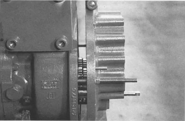 figure 57. Reducer with spool stop figure 57. Reducer with spool stop |
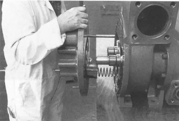 figure 58. Spool spring figure 58. Spool spring |
Rotors
39. The rotors can now be removed. (Figure 59) The XR12007J jack support is installed in the position of the rotor end cover plate (Figure 60), and the “mother” rotor is pressurized by a lifting screw. (Figure 61) The rotor will rotate because it is misaligned. (Figure 62)
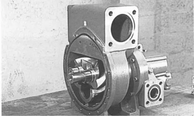 figure 59. Rotors figure 59. Rotors |
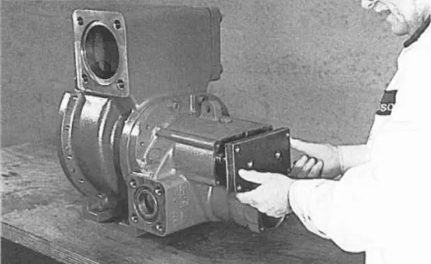 figure 60. XR12007J Jack Support figure 60. XR12007J Jack Support |
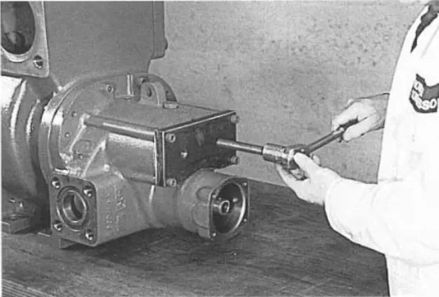 figure 61. Lifting screw figure 61. Lifting screw |
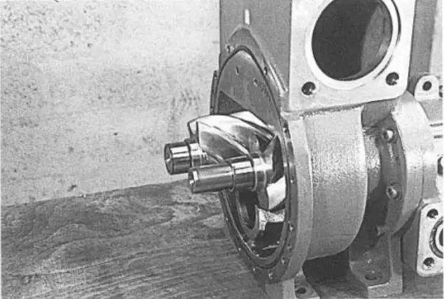 figure 62. Rotor figure 62. Rotor |
Continue to apply pressure with these lifting screws until the rotors are completely out of the thrust bearings. You can then remove the rotor by hand. (Figure 63)
40. Repeat the same procedure with the “mom” rotor. (Figure 64)
Removing the spool
41. Pull the spool out through the rotor body. (Figure 65)
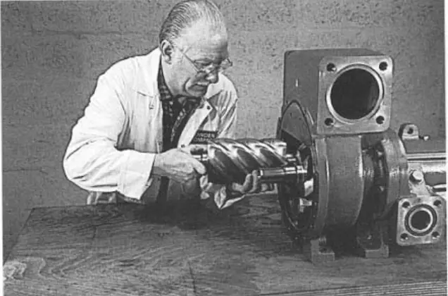 figure 63. Remove the rotor by hand figure 63. Remove the rotor by hand |
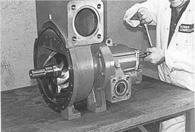 figure 64. Lifting screw pressure on the rotor figure 64. Lifting screw pressure on the rotor |
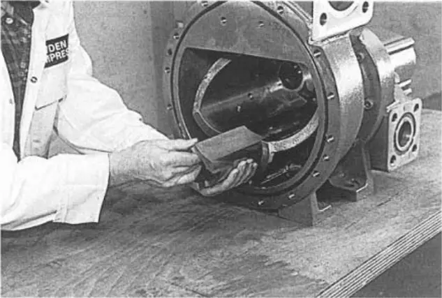 figure 65. Spool figure 65. Spool |
Angular contact bearings at the discharge end, cylindrical roller bearings and floating bushing
42. The angular contact bearings, (Figures 67 and 68), the outer treadmill and the cylindrical roller bearing holder (Figure 69) and the floating bushing (Figure 70) can then be removed from both sides (“male” and “female”) of the output cover.
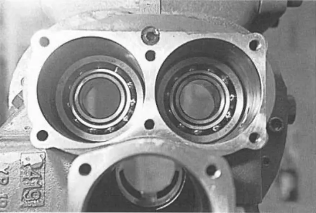 figure 67. Angular contact bearings figure 67. Angular contact bearings |
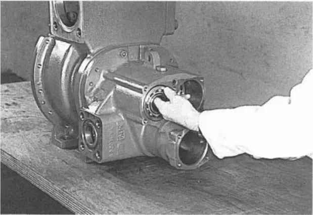 figure 68. Angular contact bearings figure 68. Angular contact bearings |
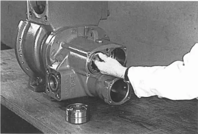 figure 69. Treadmill and cylindrical roller bearing holder figure 69. Treadmill and cylindrical roller bearing holder |
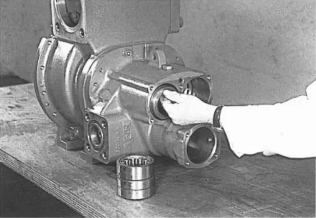 figure 70. Floating bushing figure 70. Floating bushing |
Removing the gear
43. Support the gearbox cover horizontally, with the inlet shaft pointing downwards. Remove the mounting screw and bearing washer (Figure 71).
44. Press down on the shaft to push the inner ring of the cylindrical roller bearing, the intake shaft spacer, and the gear out of the intake shaft (Figure 72).
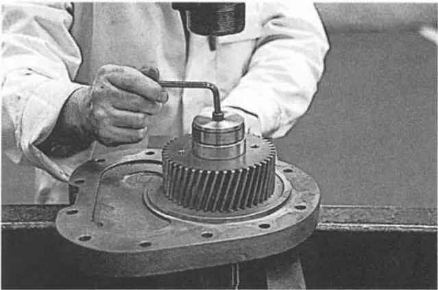 figure 71. Mounting screw and bearing washer figure 71. Mounting screw and bearing washer |
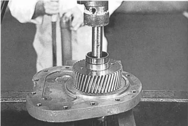 figure 72. Inner bearing ring, intake shaft spacer and gear figure 72. Inner bearing ring, intake shaft spacer and gear |
45. You can then remove the gear bush.
46. The angular contact bearing can be removed by pressing on the intake shaft (Figure 73).
Removing the bearings from the crankcase at the inlet end
47. Remove the 3 cylindrical bearings after removing the fixing spline mounting screw and washer.
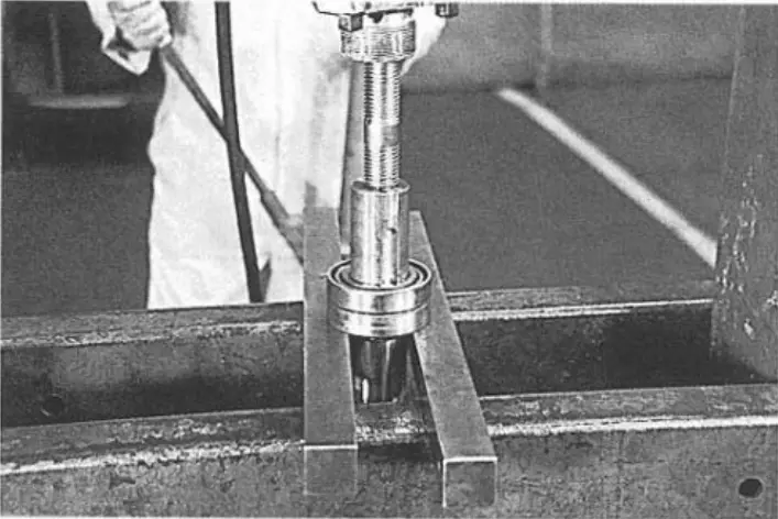 figure 73. Angular contact bearing figure 73. Angular contact bearing |
|
Continuation (Assembling the compressor)
Howden compressors
Howden XRV127 Howden XRV163 Howden XRV204 Howden WRV163 Howden WRV204 Howden WrVi255 Howden WrVi321
Technical documentation for XRV 127 compressors
XRV 127 Description XRV 127 operation Dismantling XRV 127 Assembling XRV 127 XRV 127 tools XRV 127 Parts XRV 127 schemes
Technical documentation for XRV 163-204 compressors
xrv 163-204 Description xrv 163-204 operation Dismantling XRV 163-204 XRV 163-204 assembly XRV 163-204 tools XRV 163-204 Spare Parts XRV 163-204 schemes
Technical documentation for WRV compressors - WRVi
WRV description WRV operation WRV 163 repair WRV 204-255-321 repair WRV tools WRV spare parts WRV-WRVI diagrams