- En →
- Zapchasti Kompressorov →
- Kompressory Howden →
- Sborka Xrv127 Kompressora Ch2
Toros LLC is industrial cold of Europe
Spare parts, repair and maintenance of refrigeration units.
Spare parts for compressors in stock and on order!
call:
WhatsApp
e-mail: storopov86@gmail.com
XRV 127 compressor assembly overhaul part 2
Compressor assembly procedure. Part 2.
Rotor “mom”
10. When the “mother” bearing spacer is installed, lubricate the “mother” rotor and carefully place it in the main crankcase. (Figure 115)
Use an intermediate bearing to check that the floating bushing remains in place. (Figure 116)
Rotor “dad”
11. When the “male” bearing spacer is installed, lubricate and turn the “male” rotor to align with the “female” rotor (Figure 117), making sure that the serial numbers of the rotors match.
Use an intermediate bearing to check that the floating “dad” bushing remains in place.
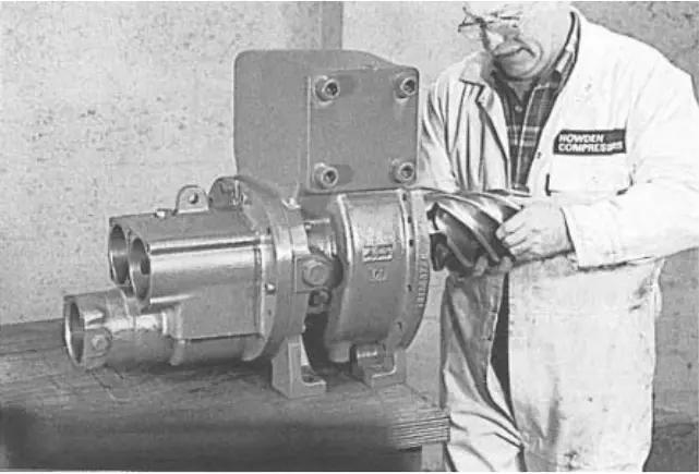 figure 115. Installing the rotor “mother” figure 115. Installing the rotor “mother” |
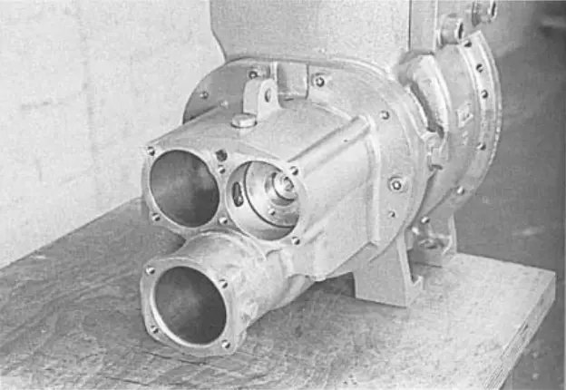 figure 116. Intermediate bearing figure 116. Intermediate bearing |
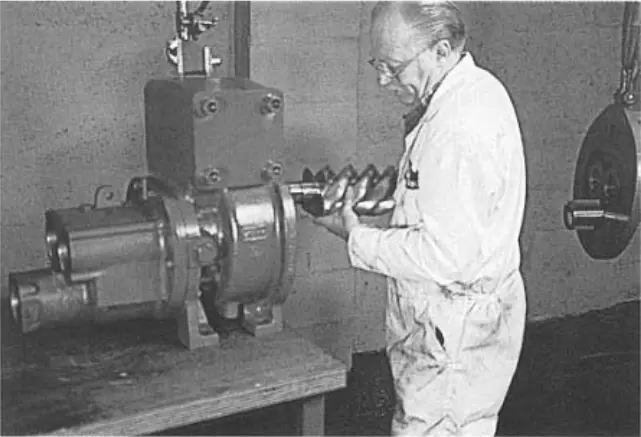 figure 117. Installing the rotor “dad” figure 117. Installing the rotor “dad” |
Stainless steel drive spring
12. During the final assembly, the spring is installed with the drive stop. (Figure 118)
Reducer sealing ring
13. Lubricate and install the gearbox sealing ring. (Figure 119)
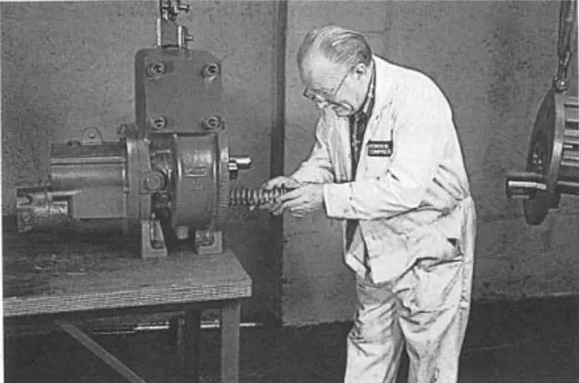 figure 118. Drive spring figure 118. Drive spring |
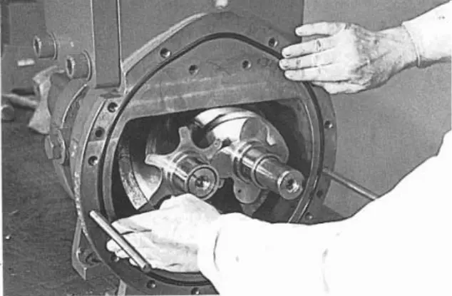 figure 119. Reducer ring figure 119. Reducer ring |
Reducer
14. Support the gearbox mass at the lifting point.
Use the M12 x 200 guide rods when assembling the gearbox on the main crankcase so that the bearing rings fall into place (so as not to damage them).
15. Attach the gearbox to the crankcase, securing the spring in the stop. (Figure 120) Use the hex nuts on the guide bars, tighten evenly until the gearbox and crankcase are connected; check that the pins are aligned and push back. (Figure 121)
Use the Loctite 243 on two internal M12 slotted mounting screws.
16. Install two M12 internal spline mounting screws and tighten to 95 Nm. (Figure 122)
17. Place the external mounting screws where possible, then remove the guide bars. (Figure 123) Tighten these slotted mounting screws to 95 Nm.
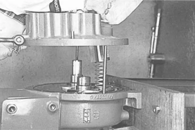 fig. 120. Reducer fig. 120. Reducer |
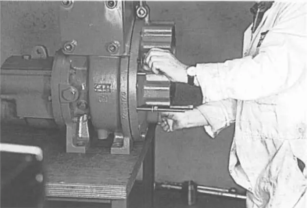 figure 121. Tightening the gearbox nuts figure 121. Tightening the gearbox nuts |
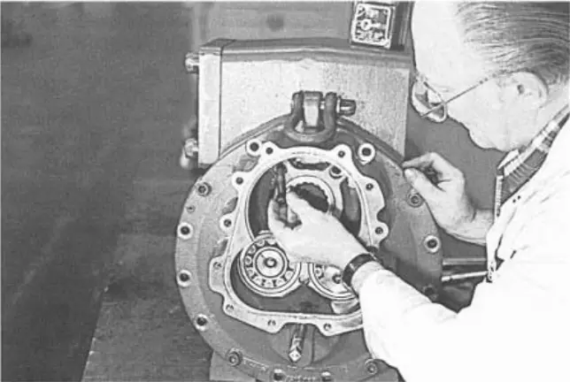 figure 122. Internal slotted mounting screws figure 122. Internal slotted mounting screws |
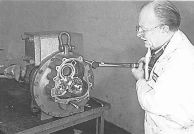 figure 123. External mounting screws figure 123. External mounting screws |
Angular contact bearing “dad”
18. Heat and insert the angular contact bearings on the “male” and “female” sides into the output casing. (Figures 124 and 125) See the assembly drawing to ensure proper alignment.
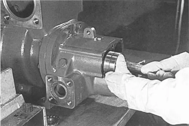 figure 124. Angular contact bearings figure 124. Angular contact bearings |
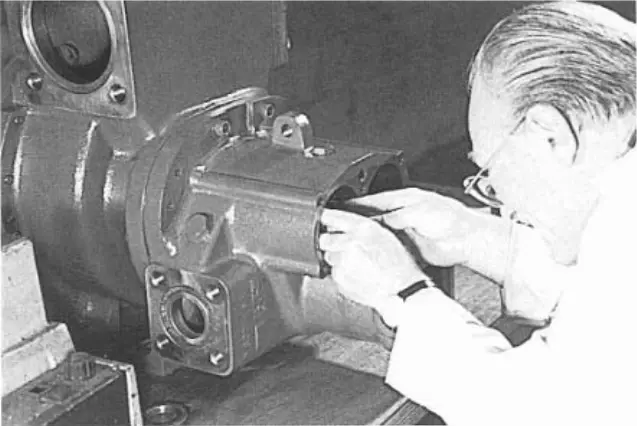 figure 125. Output cover figure 125. Output cover |
Assembling angular contact bearings (lock nut/spring washer) “dad” and “mom”
Now you need to lock the rotors using one of the methods described earlier to tighten the lock nuts. The method shown in Figure 128 consists in installing a special wrench on the “dad” rotor shaft.
19. Install the spring washer and lock nut on the “dad” rotor. (Figure 126) Tighten the lock nut to 200 Nm. (Figure 127)
20. Do the same with the “mom” rotor lock nut. (Figure 128)
21. Fold the tab on the “dad” and “mother” spring washers to secure with the XR12001J tool. (Figure 129)
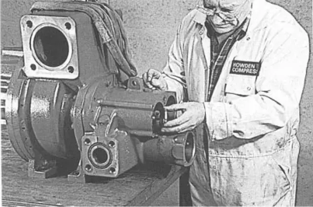 figure 126. Spring washer and lock nut figure 126. Spring washer and lock nut |
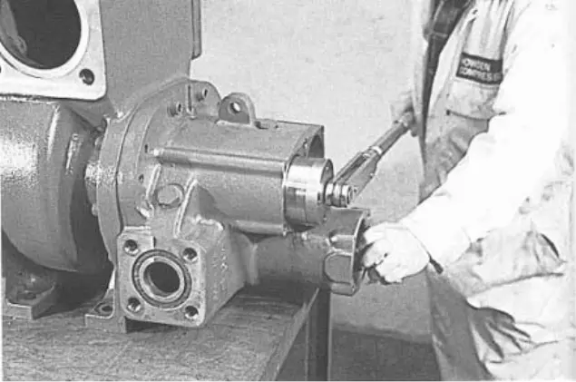 figure 127. Counternut tightening figure 127. Counternut tightening |
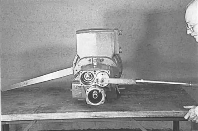 figure 128. Rotor lock nut tightening “mother” figure 128. Rotor lock nut tightening “mother” |
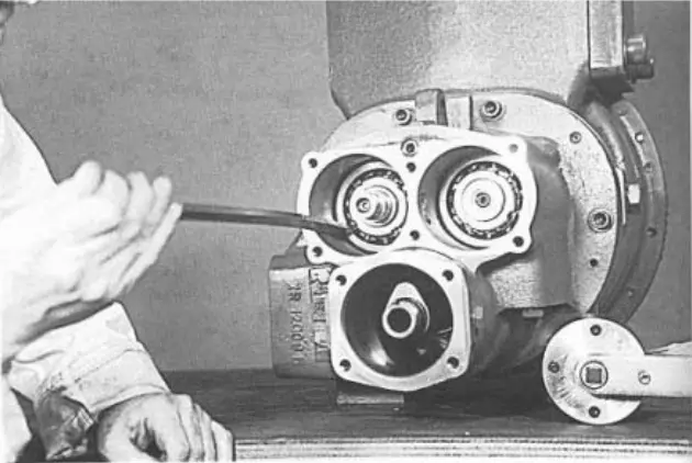 figure 129. Spring washer tab figure 129. Spring washer tab |
Discharge drum bushing (including labyrinth “dad” insert)
22. Lubricate the “dad” hole with oil and insert the discharge drum bushing. (Figures 130 and 131) Be careful not to damage the sealing ring, especially at the oil inlet, where it can be peeled off. (Figure 132)
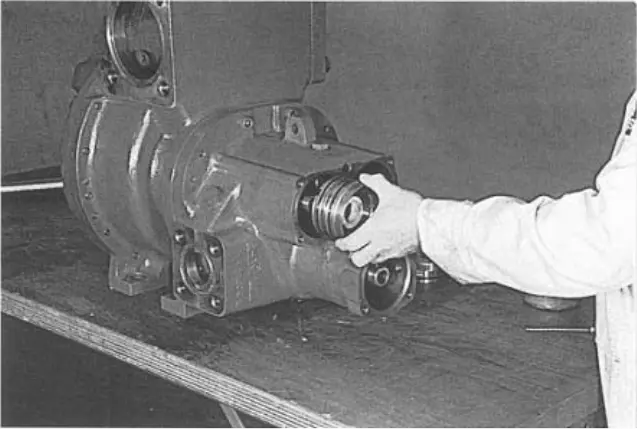 figure 130. Discharge drum bushing figure 130. Discharge drum bushing |
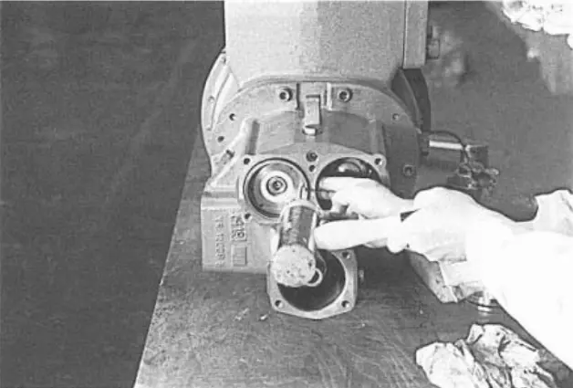 figure 131. Drum bushing figure 131. Drum bushing |
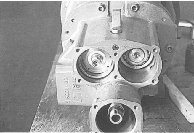 figure 132. Oil supply hole figure 132. Oil supply hole |
Discharge drum, lock nut and spring washer
23. The discharge drum can now be inserted into the hole. (Figure 133)
24. With the spring washers installed (Figure 134), replace the lock nut and tighten it to the required 130 Nm torque. (Figure 135) Fold the tab to secure it. (Figure 136)
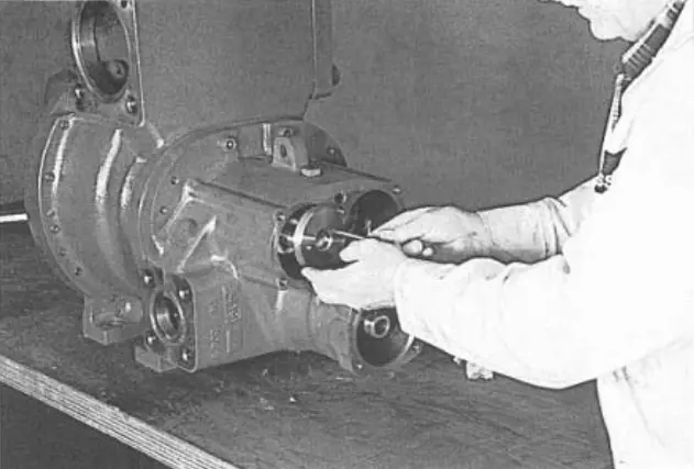 figure 133. Discharge drum figure 133. Discharge drum |
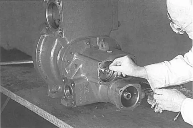 figure 134. Spring washers figure 134. Spring washers |
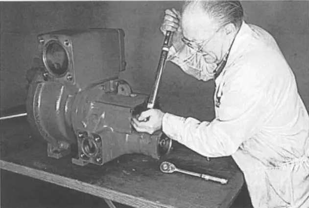 figure 135. Counternut tightening figure 135. Counternut tightening |
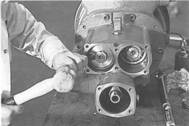 figure 136. Fixing tab figure 136. Fixing tab |
Disk spring “dad”
25. Replace the disc spring, making sure that it is well lubricated. See the drawing for the correct orientation. (Figure 137)
Rotor thrust cover “dad”
26. Lubricate and position the “dad” rotor stop cover. (Figure 138)
“Mom” spacer
27. Lubricate the “mom” end hole and insert the “mom” spacer (Figure 139) into place. (Figure 140)
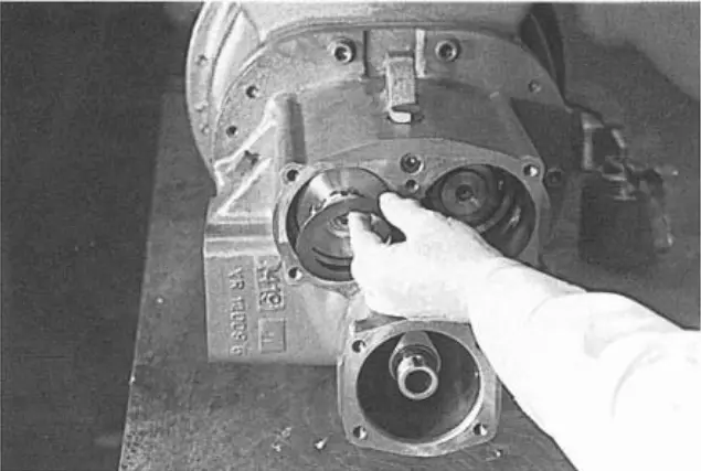 figure 137. Disc spring figure 137. Disc spring |
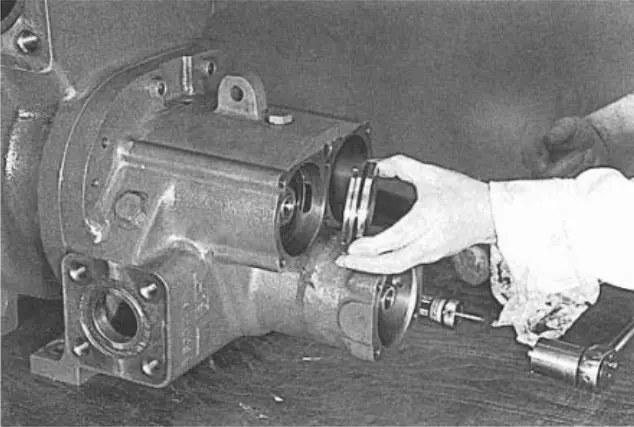 figure 138. Rotor thrust cover “dad” figure 138. Rotor thrust cover “dad” |
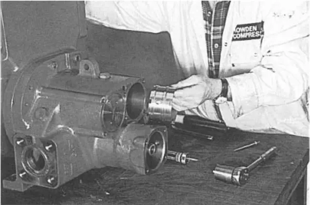 figure 139. “Mom” spacer figure 139. “Mom” spacer |
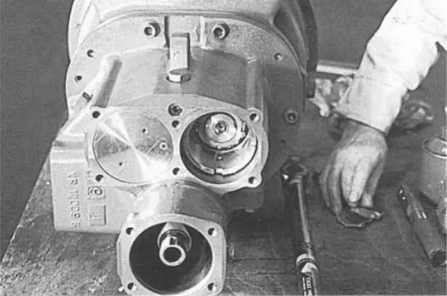 figure 140. “Mom” strut seat figure 140. “Mom” strut seat |
Disc spring “mother”
28. Lubricate and insert the “mother” disc spring. (Figure 141)
“Female” rotor thrust cover
29. Lubricate and replace the “mother” rotor stop cover. (Figure 142)
Rotor end cover plate
30. Place the rotor end cover bar on the output cover (Figure 143) and evenly tighten the slotted mounting screws and washers to 30 Nm (each screw and each washer). (Figure 144)
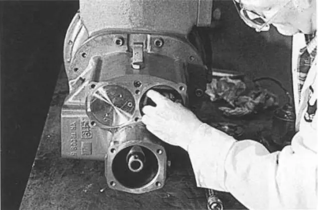 figure 141. Disc spring “mother” figure 141. Disc spring “mother” |
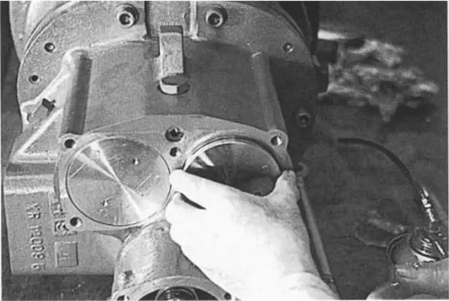 figure 142. “Female” rotor thrust cover figure 142. “Female” rotor thrust cover |
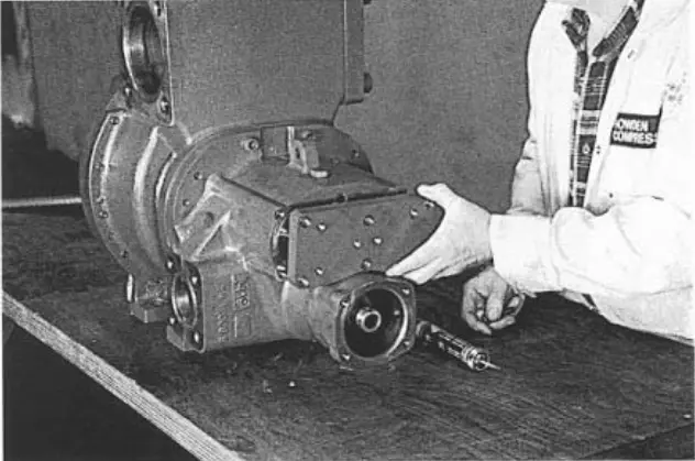 figure 143. Rotor end cover plate figure 143. Rotor end cover plate |
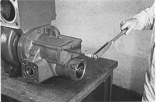 figure 144. Slotted mounting screws figure 144. Slotted mounting screws |
31. Place the indicator with a limb at the end of each rotor alternately at the end of the reducer.
32. Use Loctite 243 to screw each of the 6 slotted installation screws into the cover. (Figure 145)
At this point, check that the rotors rotate freely.
33. Tighten each adjusting screw evenly until you feel resistance. Tighten to 20 Nm (Figure 146) and then loosen them one full turn; the rotors will now move axially at the end of the crankcase. Gradually turn each set of three screws to approximately 1 Nm. This compresses the disc spring by 1.2 mm. This will also preload contact bearings with a force of about 300 N. The rotors will be axially displaced by at least 0.007 mm as a result of this preload. Check the rotor's freedom of rotation.
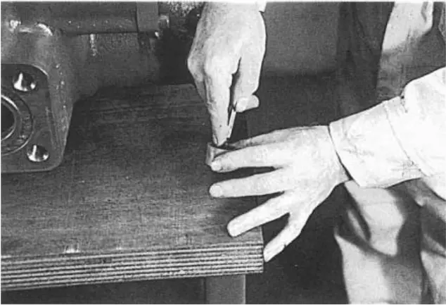 figure 145. Lubricate each Loctite 243 screw figure 145. Lubricate each Loctite 243 screw |
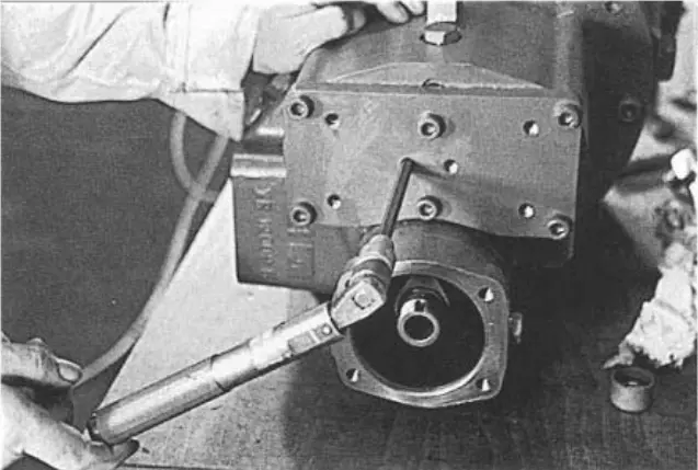 figure 146. Tightening the adjusting screws figure 146. Tightening the adjusting screws |
Drive drum
34. Lubricate both the drive drum cylinder and the drive drum. Lubricate and install the new drive drum cuff. Verify that this seal is installed correctly in a circular manner by checking the assembly drawing. Lubricate and place the new O-ring on the spool. Place the drum seal on the drum and press firmly on the outer edge of the entire sealing circumference until you hear a “click” to indicate that the seal is in place. Failure to do this will result in a preliminary breakdown of the drum seal and the compressor not working properly.
35. Replace the drive drum seal on the spool using the extraction rods without damaging the cuff. (Figure 147) Use Loctite 243 to tighten the lock nut and the spool liner thread. Use a special tool to center the drum in the cylinder hole, install the support bracket and secure the mounting screws. Insert the lock nut clutch through the bracket and tighten the lock nut to 80 Nm. Align the groove in the nut with the M5 screw hole in the drum. Use Loctite 243 to tighten a locking screw without a head into the drum. Tighten to 10 Nm.
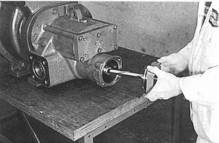 figure 147. Drive drum seal figure 147. Drive drum seal |
|
Assembling the limit switch
36. Make sure that the drive spindle pin is in place, install the indicator on the output cover.
Carefully insert the pin into the correct screw slot, which should be marked during disassembly.
37. Install four spline mounting screws in the cylinder end cover and tighten to 30 Nm.
Assembling the drive gear
38. Heat the drive gear to 80°C to 90°C (Figure 150)
39. Reassemble the drive gear hub on the “dad” rotor shaft, apply the anti-scuff compound and install the drive gear on the shaft. (Figure 151)
40. Use Loctite 243 to tighten the mounting screw and bearing washer to the required torque of 20 Nm. (Figure 152)
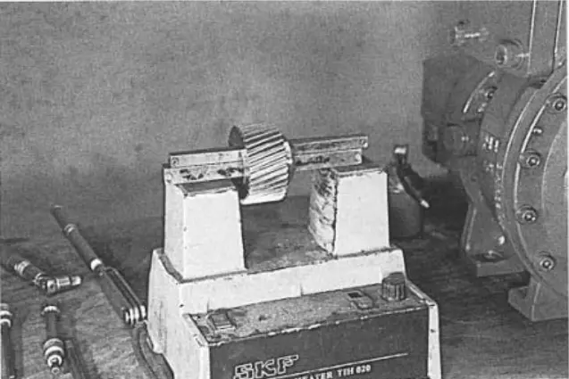 fig. 150. Driving gear fig. 150. Driving gear |
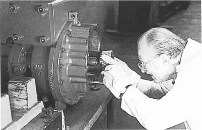 figure 151. Installing the drive gear on the shaft figure 151. Installing the drive gear on the shaft |
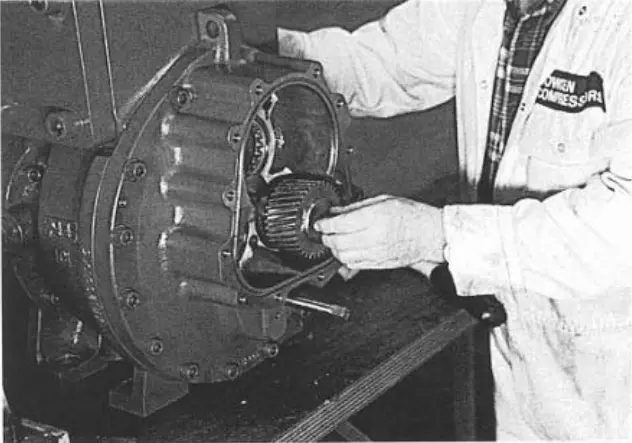 figure 152. Mounting screw and bearing washer figure 152. Mounting screw and bearing washer |
Reducer cover
41. Lubricate and install the gearbox cover O-ring. Using the guide rod to verify that the intake shaft bearings align correctly with the cylindrical roller bearings, place the cover on the gearbox. (Figure 153)
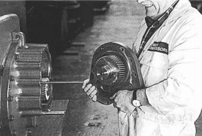 figure 153. Reducer cover figure 153. Reducer cover |
|
Shaft seal and cover
42. It is now possible to install the shaft seal by first removing the seal housing that was attached when the gearbox inlet shaft was installed on the cover. Gently lubricate the shaft and the graphite surface of the intake shaft seal and slide the intake shaft until it rests against the retaining ring. (Figure 154)
43. Use Loctite 243 to tighten each of the three screws without a rounded head. Tighten the screws slightly, evenly, on the shaft, while keeping the seal attached to the retaining ring. Finally tighten the screws to 3.5 Nm. (Figure 155)
44. Lubricate the seal seat and O-ring, and place it in a recess in the seal body.
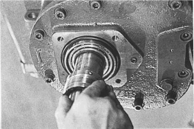 figure 154. Shaft seal figure 154. Shaft seal |
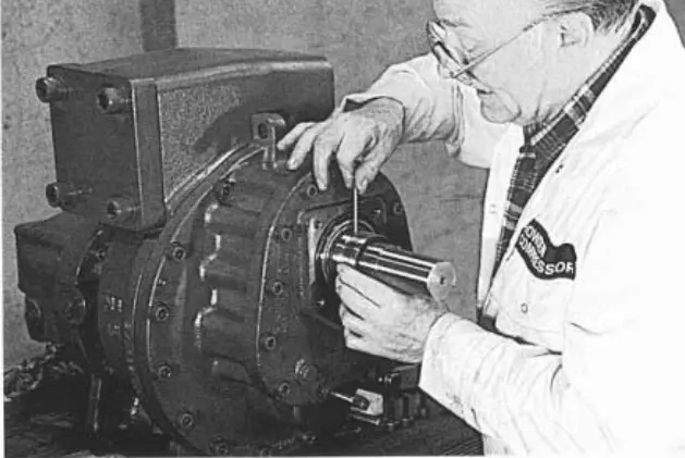 figure 155. Sealing screws figure 155. Sealing screws |
45. Lubricate and place the O-ring around the angular contact bearing in a triangular recess. Lubricate and place a small sealing ring around the oil inlet.
46. Finally, replace the seal body (Figure 156) and insert 4 splined mounting screws and washers, tighten evenly to compress and seal the shaft and o-ring to 55 Nm.
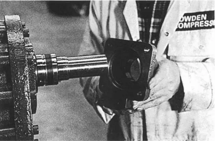 figure 156. Sealing body figure 156. Sealing body |
|
Assembling the Vi indicator
47. Check that the Vi spool stop is in position 2.6 by turning the sliding barrel fully clockwise.
Screw the indicator on the screw-in hub and check for freedom of movement.
Place the bushing lock ring on the screwed bush; check that the holes match and put it on the barrel with a sliding stop.
Place the indicator between the arrow, align it and attach it to the gearbox using one splined mounting screw.
Align the indicator arrow on the screwed bush to Vi = 2.6 and tighten the two screws to secure the screw bush to the barrel.
Use a square drive to test the grip for softness throughout the journey.
Install the indicator base plate using two mounting screws and washers.
Howden compressors
Howden XRV127 Howden XRV163 Howden XRV204 Howden WRV163 Howden WRV204 Howden WrVi255 Howden WrVi321
Technical documentation for XRV 127 compressors
XRV 127 Description XRV 127 operation Dismantling XRV 127 Assembling XRV 127 XRV 127 tools XRV 127 Parts XRV 127 schemes
Technical documentation for XRV 163-204 compressors
xrv 163-204 Description xrv 163-204 operation Dismantling XRV 163-204 XRV 163-204 assembly XRV 163-204 tools XRV 163-204 Spare Parts XRV 163-204 schemes
Technical documentation for WRV compressors - WRVi
WRV description WRV operation WRV 163 repair WRV 204-255-321 repair WRV tools WRV spare parts WRV-WRVI diagrams